

A conservator support includes the vessel connection, bracket and tank roof. FEMA highlights external attachments and their load paths [1]. Retain supporting-structure flexibility when determining the accessory response, consistent with DOE’s structural-response framework [2].
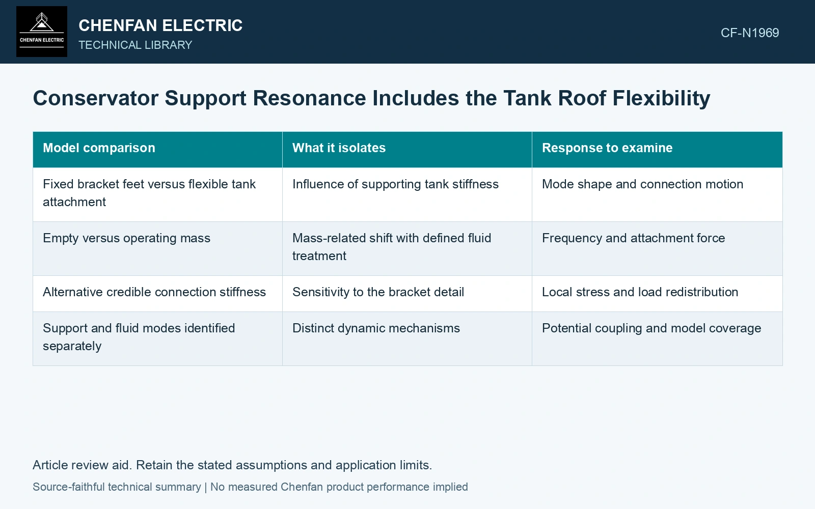
Retain the supporting structure around the attachment
Identify the tank panels, stiffeners and connections that receive the conservator load. Choose a local or coupled representation that preserves their relevant flexibility. A boundary placed too close to the bracket can create a stiff support by construction rather than by evidence.
Use the appropriate operating mass distribution, including the liquid state required for the assessment. An empty-vessel measurement can help understand the support, but it is not automatically the operating configuration. Retain internal-fluid assumptions separately when fluid dynamics are modeled.
| Model comparison | What it isolates | Response to examine |
|---|---|---|
| Fixed bracket feet versus flexible tank attachment | Influence of supporting tank stiffness | Mode shape and connection motion |
| Empty versus operating mass | Mass-related shift with defined fluid treatment | Frequency and attachment force |
| Alternative credible connection stiffness | Sensitivity to the bracket detail | Local stress and load redistribution |
| Support and fluid modes identified separately | Distinct dynamic mechanisms | Potential coupling and model coverage |
A frequency needs its mode shape
Inspect where the motion occurs and which masses participate. A low-frequency mode dominated by tank-panel bending implies a different correction from one dominated by bracket flexure. Frequency alone cannot identify which part of the support system is responsible.
Read the mode against the relevant seismic input and combine responses using the accepted assessment method. A frequency increase or decrease is not inherently an improvement; its position relative to the demand and its effect on displacement and connection force matter.
Carry the force into the local detail
Evaluate the vessel connection, support members and tank attachment with a compatible demand definition. Local weld or bolt checks should retain the directions and combinations produced by the structural assessment. A general total force can conceal a torsional or out-of-plane demand at one attachment.
Assume bracket stiffness 20 MN/m and roof stiffness 10 MN/m in series under effective mass 1,000 kg. Equivalent stiffness is 6.667 MN/m and f = 13.00 Hz; fixing the roof instead gives 22.51 Hz. Under an assumed 100 kN static diagnostic load, bracket/roof displacements are 5/10 mm, total 15 mm. Doubling bracket stiffness to 40 MN/m only reduces total to 12.5 mm, still above an assumed 12 mm diagnostic cap. Resolve roof flexibility or the complete layout instead of continuing to stiffen the bracket alone. Dynamic support demand and fluid modes remain separate checks.
Change the flexible segment identified by the mode shape, then reassess the attachment demand. Stiffening a bracket may achieve little if tank-roof motion dominates. Keep the fluid response separate: a sloshing calculation cannot establish the strength or stiffness of the structural support.
References
- FEMA and Applied Technology Council, FEMA E-74, Reducing the Risks of Nonstructural Earthquake Damage—A Practical Guide, December 2012, section 6.4.7.3, Transformers.
- U.S. Department of Energy, DOE-STD-1020-2016, Natural Phenomena Hazards Analysis and Design Criteria for DOE Facilities, 2016, sections 3.5 and 3.6.