

Grout beneath a transformer base participates in its load path. FEMA discusses transformer anchorage [1]; DOE guidance calls for a continuous traceable path to the foundation [2]. An unsupported region changes the evidenced bearing condition.
Describe the support that is actually evidenced
Record grout geometry, installation sequence, accessible inspection locations and the support assumptions in the equipment model. Distinguish a visible perimeter from the concealed bearing area. Photographs of the outside edge cannot establish uniform contact under an inaccessible plate.
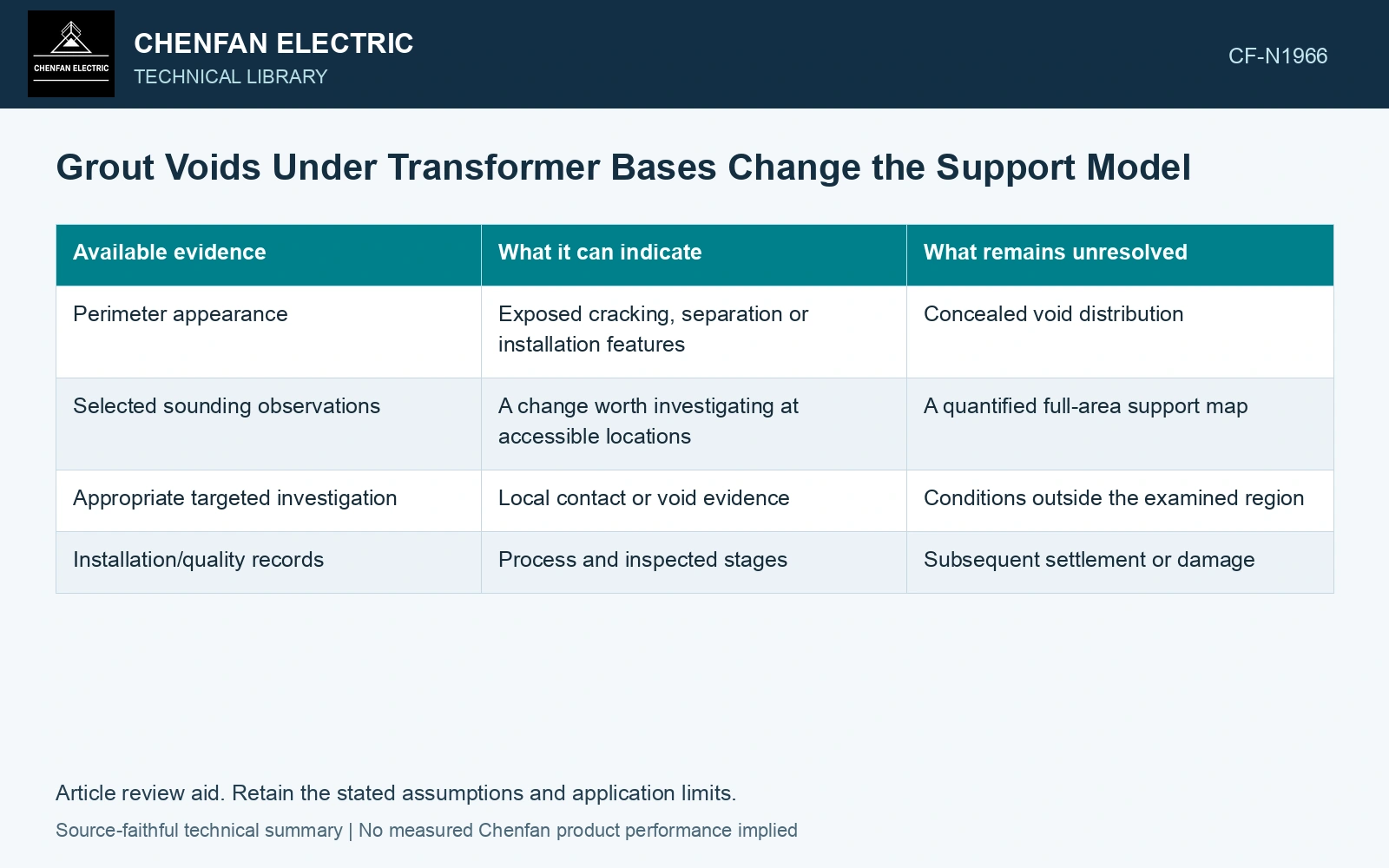
| Available evidence | What it can indicate | What remains unresolved |
|---|---|---|
| Perimeter appearance | Exposed cracking, separation or installation features | Concealed void distribution |
| Selected sounding observations | A change worth investigating at accessible locations | A quantified full-area support map |
| Appropriate targeted investigation | Local contact or void evidence | Conditions outside the examined region |
| Installation/quality records | Process and inspected stages | Subsequent settlement or damage |
Examine a credible unsupported region
Use a support map or justified bounding cases in the baseplate assessment. Check plate bending, contact pressure and anchor demand together. A small unsupported region near a highly loaded connection can matter differently from the same area in a lightly loaded part of the footprint.
Retain the plate stiffness and actual connection geometry. A rigid-plate assumption can distribute force differently from a plate that bends between bearing zones. Local anchor bending or prying should be considered where the detail and deformation make those mechanisms relevant; they should not be inserted as an arbitrary multiplier.
Select inspection for the question it must resolve
Sounding, imaging or a targeted intrusive method has access and interpretation limits. Choose an investigation with the structural and installation teams, identifying the region and uncertainty that affect the decision. The aim is not to label the whole installation sound from a few convenient observation points.
Compare the evidenced contact case with the original full-support model. Identify which demands change materially and which assumptions dominate. If uncertainty remains, carry it into the support envelope rather than replacing unknown contact with full bearing.
Assume a 1.0 m² bearing area carries 200 kN: uniform average pressure is 0.20 MPa. An assumed void removing 25% of contact leaves 0.75 m² and average 0.267 MPa. Against an assumed 0.25 MPa bearing-screen cap, the full-area model passes and reduced area fails even before edge concentrations. Investigate the actual bearing map, plate stiffness and attachment demand; tightening anchors cannot establish missing support. The cap is a teaching input, not a grout strength or code resistance.
Connect every investigated grout region to the bearing area used in the model. If a consequential area remains unobserved, carry that uncertainty into the demand envelope or investigate it further. The perimeter appearance cannot resolve a support assumption beneath the center of the plate.
References
- FEMA and Applied Technology Council, FEMA E-74, Reducing the Risks of Nonstructural Earthquake Damage—A Practical Guide, December 2012, section 6.4.7.3, Transformers.
- U.S. Department of Energy, DOE-STD-1020-2016, Natural Phenomena Hazards Analysis and Design Criteria for DOE Facilities, 2016, sections 3.5 and 3.6.