

ABB describes combined CT–VT construction sharing one unit [1]. Retain both electrical sources and their common surroundings when evaluating simultaneous duty; compact packaging does not establish thermal independence.
CT conductor/joint/winding heat and VT excitation/burden heat can enter common oil and supports. Dong et al. model conductor Joule heating and heat transfer in a particular distribution CT [2]; that method does not qualify this HV combined assembly.
Vary current and voltage independently
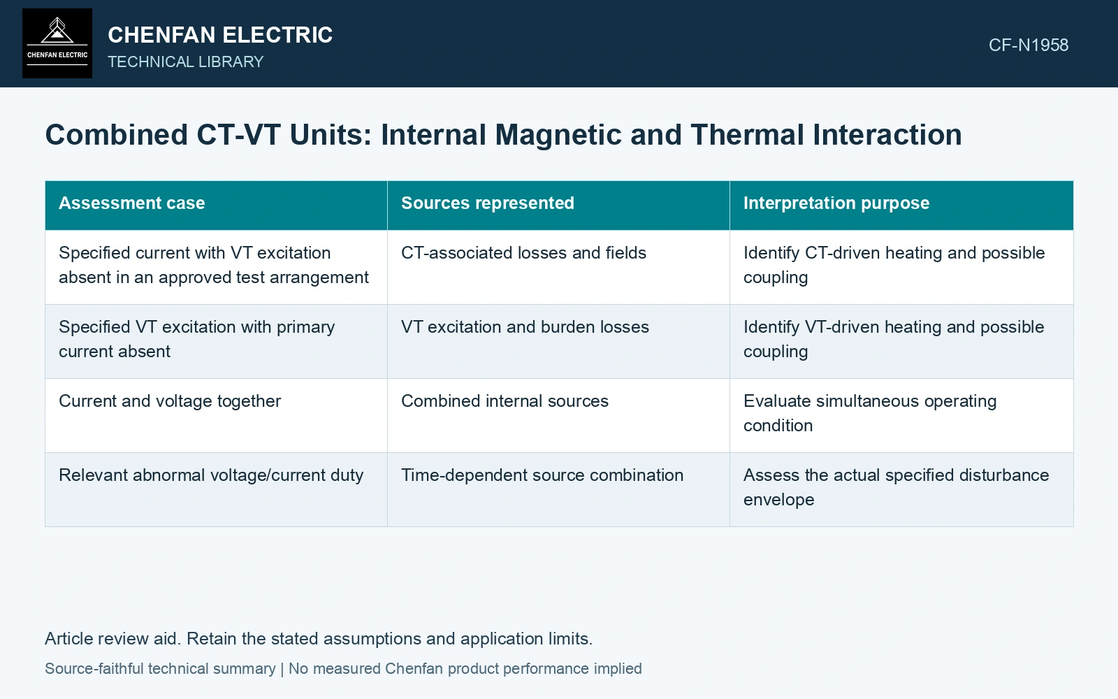
Use an excitation matrix to distinguish the source of a measured response. A CT-only or VT-only development test may help identify a mechanism, but the service case can contain both inputs. Preserve secondary burdens and circuit configuration for each observation.
| Assessment case | Sources represented | Interpretation purpose |
|---|---|---|
| Specified current with VT excitation absent in an approved test arrangement | CT-associated losses and fields | Identify CT-driven heating and possible coupling |
| Specified VT excitation with primary current absent | VT excitation and burden losses | Identify VT-driven heating and possible coupling |
| Current and voltage together | Combined internal sources | Evaluate simultaneous operating condition |
| Relevant abnormal voltage/current duty | Time-dependent source combination | Assess the actual specified disturbance envelope |
This matrix defines evidence questions, not field energization instructions. The manufacturer must determine valid test arrangements.
Heat-source addition does not guarantee temperature addition
In a linear thermal model with unchanged boundaries, source contributions can be superposed. In an actual oil-paper assembly, fluid motion and material properties can change with temperature. Simply adding two separately measured temperature rises may therefore misrepresent the simultaneous case.
Trace each source to the potentially limiting insulation region. The CT primary joint may warm the upper region, while the VT core warms the lower oil. Circulation can couple those regions even when neither single-source test reaches a limit. Shared tank temperature alone may conceal the local combination.
Review the screens as installed
Screens must retain their intended electric potential and current paths. Nearby CT current can also induce effects in conducting structures, depending on their geometry and connectivity. A screen chosen for field control should be evaluated within the combined arrangement, including any unintended closed conducting path.
Electrical response measurements should identify which input was varied and which output changed. A change in VT error under higher primary current could arise from thermal drift or electromagnetic coupling; the excitation matrix helps separate those explanations. Do not assign a mechanism from correlation alone.
Assume CT/VT dissipations 10/15 W and linear sensitivities to one monitored insulation point 0.5/0.8 K/W, unchanged under combined duty. Standalone rises are 5/12 K; simultaneous rise is 17 K. Against an assumed 15 K local-rise cap, separate tests pass but the combined screen fails. Hold qualification until simultaneous source, actual cooling and local temperature are validated. Linear thermal addition neither proves the coefficient remains valid after circulation changes nor establishes absent magnetic interaction.
When evidence from separate component tests is used, identify the shared assembly effects it does and does not cover. The resulting assessment should account for simultaneous excitation, burdens and cooling in the manufactured unit, rather than treating a compact combined housing as proof that two independent test reports describe the same service condition.
References
- ABB, Instrument Transformers Application Guide, publication 1HSM 9543 40-00en, Edition 4, February 2015, sections 5.1–5.6, 6.1 and 7.1.
- B. Dong et al., Three-Dimensional Electro-Thermal Analysis of a New Type Current Transformer Design for Power Distribution Networks, Energies 14, 1792, 2021. DOI: 10.3390/en14061792.