

A cascaded inductive VT divides electromagnetic and insulation functions between stages. ABB’s construction discussion identifies cascade VTs [1]; map the actual main/coupling windings, cores and their references instead of treating a stage name as a complete circuit.
ABB’s application guide describes cascade construction as an option for higher-voltage inductive VTs. For insulation review, the manufacturer’s actual schematic and section drawing are more useful than a simplified description of one transformer feeding another. [1]
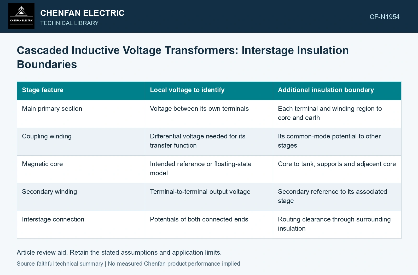
Assign a potential to every relevant node
Start with the primary terminals and earth reference. Add each core, screen, main winding terminal and coupling-winding terminal. Mark whether a potential is fixed by a connection, follows a designed intermediate reference or is determined by capacitive coupling. A floating part should not be assigned zero voltage merely because it has no external terminal.
| Stage feature | Local voltage to identify | Additional insulation boundary |
|---|---|---|
| Main primary section | Voltage between its own terminals | Each terminal and winding region to core and earth |
| Coupling winding | Differential voltage needed for its transfer function | Its common-mode potential to other stages |
| Magnetic core | Intended reference or floating-state model | Core to tank, supports and adjacent core |
| Secondary winding | Terminal-to-terminal output voltage | Secondary reference to its associated stage |
| Interstage connection | Potentials of both connected ends | Routing clearance through surrounding insulation |
Local differential voltage is only part of the duty
A winding can have a modest voltage between its terminals while both terminals sit at a substantial common-mode potential to earth. Its insulation to the core and tank must reflect that common mode. The core-to-core boundary can face a different duty again.
Keep voltage quantities on a consistent basis. Power-frequency RMS phasors cannot be mixed directly with impulse peaks. If adjacent stage potentials differ in phase, subtract phasors before calculating the differential rather than subtracting their RMS magnitudes.
Check transient division independently
During a fast transient, charge storage in winding and stray capacitances affects initial potentials; the basic capacitance relation is Q = CΔV [2]. Equal power-frequency division does not determine that initial capacitive division. Use actual routing, references and transient circuit elements.
Check the sensitivity to a changed screen connection or interstage lead route. A connection that preserves the nominal transformation ratio can still change a local transient insulation stress. That is why both schematic connectivity and physical routing belong in the review.
Assume two nodes are 40 and 80 kV RMS to earth, sinusoidal, in phase and at 50 Hz. Their differential is 40 kV RMS, but an upper-stage support to earth still faces 80 kV RMS. With a fictional 60 kV RMS support-screen cap, using only the differential would falsely pass. Hold the support/field design until each actual node-to-earth duty is resolved. Do not transfer the equal steady-stage shares to impulse peaks: build the corresponding capacitance/transient network separately.
The completed map should let the reviewer trace an applied voltage through the main sections, identify how the output reaches its reference and locate every interstage and stage-to-earth insulation boundary. Any node whose potential remains undefined is a modelling gap that should be resolved before assigning an insulation level to the cascade assembly.
References
- ABB, Instrument Transformers Application Guide, publication 1HSM 9543 40-00en, Edition 4, February 2015, sections 5.1–5.6, 6.1 and 7.1.
- U.S. Department of Energy, DOE-HDBK-1011/2-92, Electrical Science, Volume 2, 1992.