

Modern meters and relays can impose a small burden on an inductive VT. Lower secondary current reduces winding loss associated with those loads, but the primary remains energized. Excitation loss and the interaction between the VT and network therefore remain part of the thermal review. [1] [2]
A very small metering burden is neither proof of instability nor proof that every thermal risk has disappeared. The useful assessment separates the losses and then examines the operating states that can change them.
Identify the heat sources at light load
Core loss follows the excitation voltage, frequency, waveform and core state. Primary excitation current also contributes winding loss. Secondary load adds its own current-dependent losses, while any connected damping device can dissipate heat under particular voltage conditions.
Keep the actual instrument-transformer construction, winding arrangement and insulation boundaries explicit in the review. Qualify the represented assembly rather than inferring an internal feature from its external appearance.
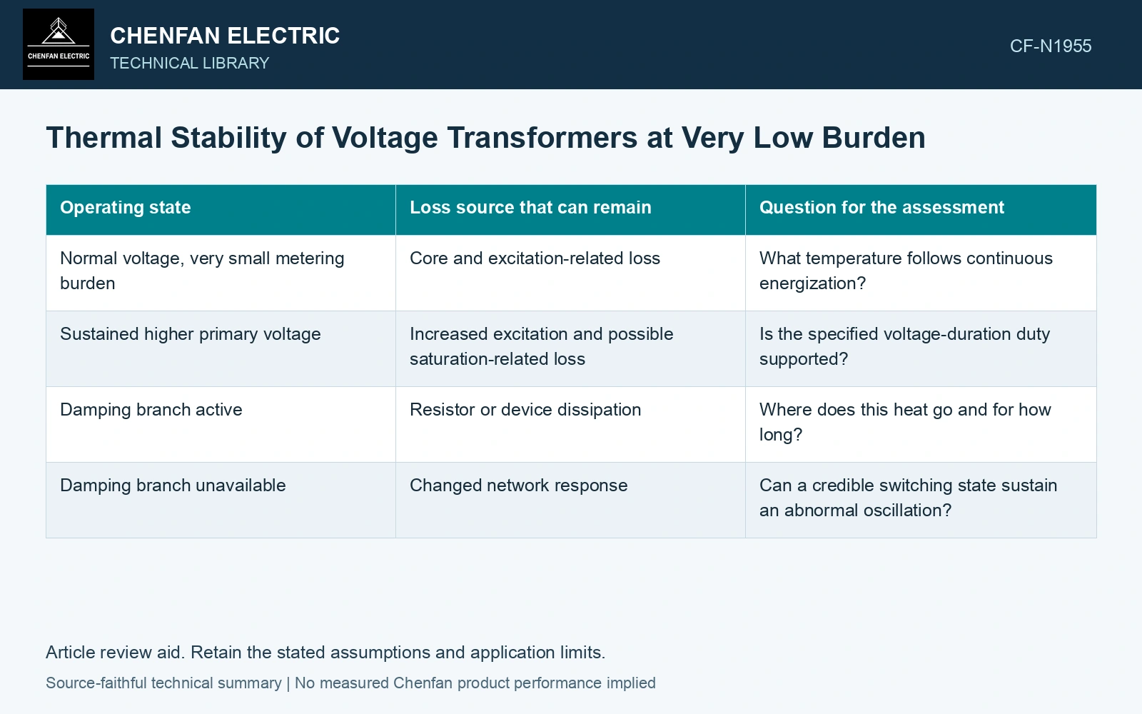
| Operating state | Loss source that can remain | Question for the assessment |
|---|---|---|
| Normal voltage, very small metering burden | Core and excitation-related loss | What temperature follows continuous energization? |
| Sustained higher primary voltage | Increased excitation and possible saturation-related loss | Is the specified voltage-duration duty supported? |
| Damping branch active | Resistor or device dissipation | Where does this heat go and for how long? |
| Damping branch unavailable | Changed network response | Can a credible switching state sustain an abnormal oscillation? |
Keep capacitance in the network model
ABB’s guide describes ferroresonance as an interaction between nonlinear inductance and capacitance under particular network conditions. For an inductive VT, relevant capacitance can be external to the VT, including connected cables or switchgear arrangements. A low burden can alter damping, but it does not determine the outcome by itself. [1]
Use the actual grounding, switching and capacitance configuration. Compare credible states such as an isolated phase or a changed connection only where they can occur in the installation. A nominal steady-state load flow does not establish nonlinear stability following switching.
Do not add burden without evaluating the consequence
An added damping circuit may improve one dynamic condition while creating a continuous or fault-duration heat source. The circuit design must account for its own thermal duty, influence on measurements and failure state. A generic statement that a resistor solves light-load operation leaves those questions unanswered.
Assume a VT draws 12 W internal loss at its rated voltage and dissipates another 18 W in a connected burden. Removing that burden reduces external power but need not reduce the 12 W internal source. If the relevant internal thermal conductance is assumed 0.40 W/K, that source alone gives a 30 K rise. Evaluate the actual low-burden magnetic and circuit state rather than predicting near-ambient temperature from the smaller output VA. Retain the damping branch and ferroresonance assessment in that comparison.
Compare the thermal calculation with applicable test evidence at the stated voltage, frequency and circuit configuration. If the instrumentation upgrade removes an old load, update the network and thermal models rather than assuming the lower VA number automatically validates the revised installation. The decision then follows from the remaining heat sources and demonstrated operating states, not from the metering burden alone.
References
- ABB, Instrument Transformers Application Guide, publication 1HSM 9543 40-00en, Edition 4, February 2015, sections 3.4 and 4.9–4.12.
- U.S. Department of Energy, DOE-HDBK-1012/2-92, Thermodynamics, Heat Transfer, and Fluid Flow, Volume 2, 1992.