

A high-voltage current transformer can contain several magnetic cores, each with its own secondary winding and assigned function. The same primary conductor passes through their magnetic windows. This shared current path does not make the cores, leads and screens interchangeable in the assembly. [1]
A CT may contain several separate cores and secondary windings linked by one primary path. Map each winding envelope and terminal route, keeping the assigned measurement or protection function tied to its physical core. [2]
Map the occupied envelope
For every core, identify the magnetic window, winding build, insulation allowance, support and any associated screen. The winding envelope can be larger than the bare core envelope. A layout that fits magnetic steel alone may leave too little space for turns, crossover leads or the graded insulation around the assembly.
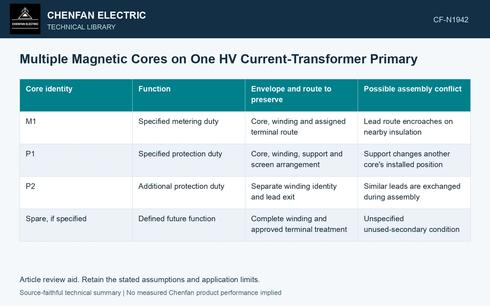
| Core identity | Function | Envelope and route to preserve | Possible assembly conflict |
|---|---|---|---|
| M1 | Specified metering duty | Core, winding and assigned terminal route | Lead route encroaches on nearby insulation |
| P1 | Specified protection duty | Core, winding, support and screen arrangement | Support changes another core’s installed position |
| P2 | Additional protection duty | Separate winding identity and lead exit | Similar leads are exchanged during assembly |
| Spare, if specified | Defined future function | Complete winding and approved terminal treatment | Unspecified unused-secondary condition |
These are illustrative identities, not a recommended number or rating of cores. Retain the actual manufacturer’s labels and terminal convention.
Shared linkage leaves local geometry unresolved
In an ideal CT model, a primary turn linking a core contributes the same primary ampere-turns regardless of modest conductor displacement within the window. Real geometry also includes leakage fields, return conductors, magnetic joints and nearby metal. Those features can affect local flux distribution without changing the nominal turn count.
A conductor that passes centrally through one core may be closer to another core’s inner surface after routing through the full stack. Record the offset at each core plane. A single overall ‘conductor centred’ dimension cannot describe a bent or stepped route.
Keep lead routing in the insulation model
Secondary conductors must reach their terminals through the intended low-voltage route. A lead diverted around an assembly obstruction can cross a screened boundary or reduce clearance to a primary-connected part. Its functional label does not protect it from the local electric field.
Check magnetic, electrical and mechanical drawings against the same core-position map. Changing the order of cores to solve a packaging problem can alter lead routes and screen connections even when the individual core specifications stay unchanged.
Assume three GOES cores each use catalogue 0.23 mm laminations. [3] Layer counts of 100, 120 and 140 give nominal steel stack widths of 23.0, 27.6 and 32.2 mm, totalling 82.8 mm. If the insulated winding/support envelope is assumed to add 10 mm per core and two 5 mm inter-core spacings, installed axial demand is 122.8 mm. Against an assumed 120 mm available space it fails by 2.8 mm, although the bare steel fits easily. Rebuild the complete envelopes and lead routes before changing core order or reducing a spacing.
Sheet count, winding build, core-order identity, support seating and terminal routing establish the final package. Retain the core-specific test mapping after any rearrangement of the active parts.
Once the final arrangement is frozen, match each test result to the installed core identity. That closes the gap between a specification listing several acceptable cores and a manufactured CT in which each core occupies the intended space, links the intended primary path and reaches the correct terminals.
References
- IEC, IEC 61869-2:2012, Instrument transformers — Part 2: Additional requirements for current transformers.
- ABB, Instrument Transformers Application Guide, publication 1HSM 9543 40-00en, Edition 4, February 2015, sections 3.4 and 4.9–4.12.
- Nippon Steel Corporation, Grain-Oriented Electrical Steel Sheets, catalogue D004je, April 2020, specification and typical-property tables.