

A gas-to-air cooler has gas-film, wall and air-film resistances in series. DOE describes series heat paths and the overall heat-exchanger relation [1]. Wu et al.’s particular gas-transformer thermal study [2] does not supply the UA or fan performance of another installed cooler.
Describe the cooler’s installed gas and air circuits. Include density, inlet temperatures, flow distribution and the surrounding room or outdoor airflow.
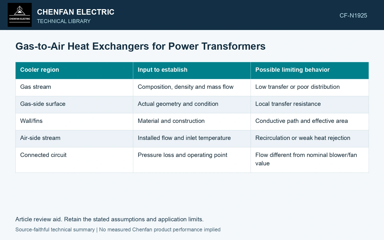
Separate the resistances
| Cooler region | Input to establish | Possible limiting behavior |
|---|---|---|
| Gas stream | Composition, density and mass flow | Low transfer or poor distribution |
| Gas-side surface | Actual geometry and condition | Local transfer resistance |
| Wall/fins | Material and construction | Conductive path and effective area |
| Air-side stream | Installed flow and inlet temperature | Recirculation or weak heat rejection |
| Connected circuit | Pressure loss and operating point | Flow different from nominal blower/fan value |
A component curve must be interpreted at its recorded fluid and configuration. A catalog result at another gas state is not automatically equivalent.
Use an overall heat relation on its basis
Under a suitable steady heat-exchanger model, Q = UAΔTlm. Q is heat transfer in watts, U an overall coefficient in watts per square metre-kelvin, A the matching area in square metres and ΔTlm the logarithmic mean temperature difference in kelvins. Its use requires appropriate flow arrangement and correction where necessary.
The equation does not supply U. Gas properties, flow and geometry determine the coefficient. Nor does it establish local winding temperature upstream of the cooler.
Couple flow to pressure loss
The gas blower operates against the complete circuit, including cooler and winding paths. Changing a cooler can alter pressure loss and therefore circulation. A larger surface area can introduce another hydraulic tradeoff; its thermal benefit needs the resulting operating point.
Air fans similarly interact with installed ducts, screens and room boundaries. Exhaust recirculation raises inlet temperature and reduces the available driving difference.
Compare gas states explicitly
Mass flow equals density times volumetric flow at the stated boundary. A low-density condition can therefore change heat transport even if a volumetric reading appears similar. The qualified design should use an appropriate equation of state and relevant transport properties.
Assume gas-side thermal resistance 0.00100 K/W, combined wall/air-side resistance 0.00025 K/W and effective ΔTlm = 25 K. Total resistance 0.00125 K/W gives UA = 800 W/K and 20 kW [1]. Halving only the wall/air term gives 22.22 kW, +11.1%; halving the gas term gives 33.33 kW, +66.7%, at unchanged ΔTlm. This assumed comparison prioritises the gas side, not a larger air fan. Recompute flow, inlet temperatures and pressure losses after a change; the fixed driving difference and assigned resistances do not qualify winding temperatures.
The assessment should identify the controlling resistance and show what a proposed change actually affects. This can justify a fan, gas-flow or exchanger revision where evidence supports it. It also prevents an expensive air-side change from being credited with a cooling improvement that the remaining gas-side bottleneck cannot deliver.
References
- U.S. Department of Energy, DOE-HDBK-1012/2-92, Thermodynamics, Heat Transfer, and Fluid Flow, Volume 2, 1992.
- Y. Wu et al., Research on Heat Dissipation Performance of Eco-friendly Gas insulated Transformer with i-C4F7N/CO2 as the Insulation Medium, Journal of Physics: Conference Series 2527, 012011, 2023. DOI: 10.1088/1742-6596/2527/1/012011.