

An SST and a conventional transformer can serve the same voltage change while providing different control and protection behavior. One can also combine functions otherwise supplied by converters, regulators or storage interfaces. Comparing their enclosures alone can therefore compare different services.
Define the required application first. Then draw the complete equipment boundary for each alternative, including any additional conversion and protection needed to meet that application.
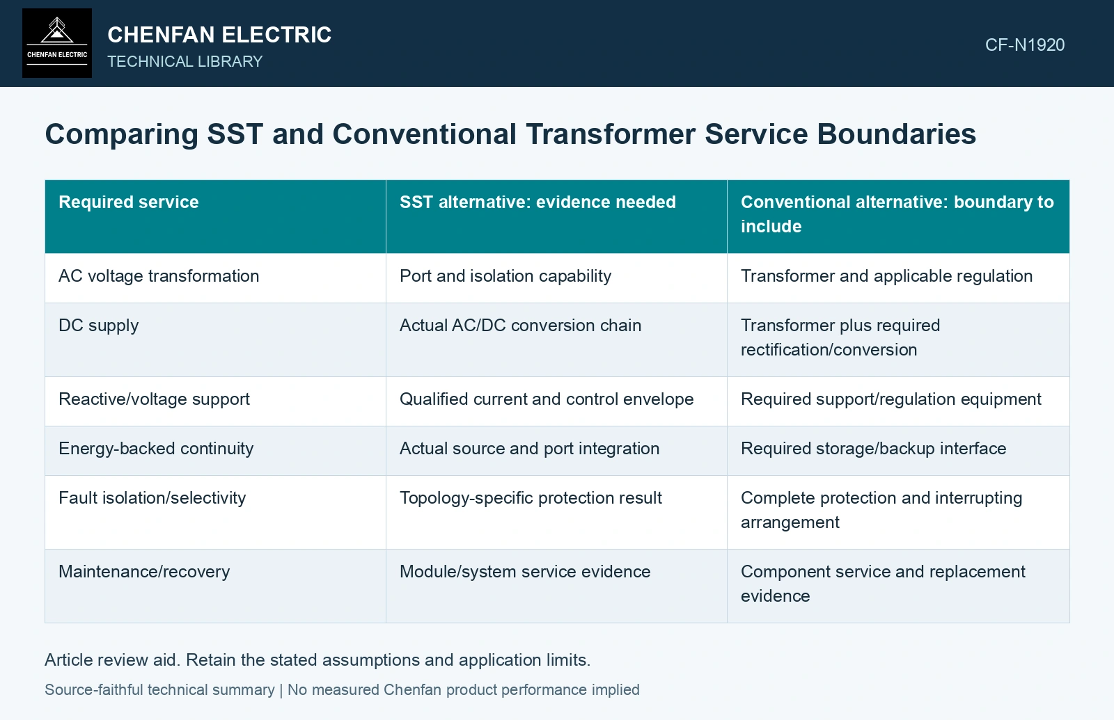
Compare equal functions
| Required service | SST alternative: evidence needed | Conventional alternative: boundary to include |
|---|---|---|
| AC voltage transformation | Port and isolation capability | Transformer and applicable regulation |
| DC supply | Actual AC/DC conversion chain | Transformer plus required rectification/conversion |
| Reactive/voltage support | Qualified current and control envelope | Required support/regulation equipment |
| Energy-backed continuity | Actual source and port integration | Required storage/backup interface |
| Fault isolation/selectivity | Topology-specific protection result | Complete protection and interrupting arrangement |
| Maintenance/recovery | Module/system service evidence | Component service and replacement evidence |
The table asks what the application needs. It does not assume every SST supplies every function, or that each conventional arrangement needs the same added equipment.
Use one operating duty for losses
Compare loss across load, voltage, reactive service and idle modes under a common measurement boundary. Include auxiliary and cooling power consistently. A peak-efficiency point cannot establish annual energy use.
For an AC/DC application, excluding the conventional rectifier while including it inside the SST would bias the comparison. Conversely, assigning an unnecessary converter to the conventional alternative can make the SST look favorable by construction.
Keep fault behavior visible
SST current limiting changes the fault current available to downstream protection. Include the required protection equipment with verified coordination for the installation in the complete-system comparison. [1]
A control function also needs a credible failure state. Review what service remains after a module, sensor or auxiliary supply fails, and how recovery occurs.
Compare maintainable systems
Include service skills, replacement compatibility, required isolation and the evidence supporting continued operation. Modularity can aid replacement, but it does not prove universal interchangeability or uninterrupted repair. A conventional component’s familiarity is likewise not proof that it meets every new control objective.
Huber and Kolar identify complete-system efficiency and protection as SST design challenges. Compare equivalent service functions and physical power paths, then include all stages and auxiliaries required at the installation boundary. [1][2]
Assume the conventional transformer boundary delivers 1,000 kWh while losing 10 kWh, whereas an SST boundary delivers the same output with 8 kWh conversion loss and 5 kWh auxiliary energy. Overall efficiencies are 1,000/1,010 = 99.01% and 1,000/1,013 = 98.72%. Excluding SST auxiliaries would instead report 99.21% and reverse the ranking. Define all included ports, standby periods and cooling supplies before comparing service options; magnetic isolation and controllable power ports do not make the energy-accounting boundaries automatically equivalent.
The purchasing conclusion should identify the functions and operating cases in which each complete alternative is qualified. It can then compare footprint, loss and lifecycle implications on the same service basis. That is a defensible engineering choice; size or one efficiency percentage cannot establish that either technology replaces the other in every application.
References
- J. E. Huber and J. W. Kolar, Solid-State Transformers: On the Origins and Evolution of Key Concepts, IEEE Industrial Electronics Magazine 10(3), 2016. DOI: 10.1109/MIE.2016.2588878.
- D.-M. Predescu and Ș.-G. Roșu, Solid State Transformers: A Review—Part I: Stages of Conversion and Topologies, Technologies 13, 74, 2025. DOI: 10.3390/technologies13020074.