

A replacement SST module fits the frame and uses the same connectors. Its hardware revision, firmware, calibration or limit settings can still differ from the modules around it. In a balanced modular converter, those differences may change voltage allocation, current sharing or protection response.
The replacement record should identify a verified system configuration, not just a part number that appears mechanically compatible.
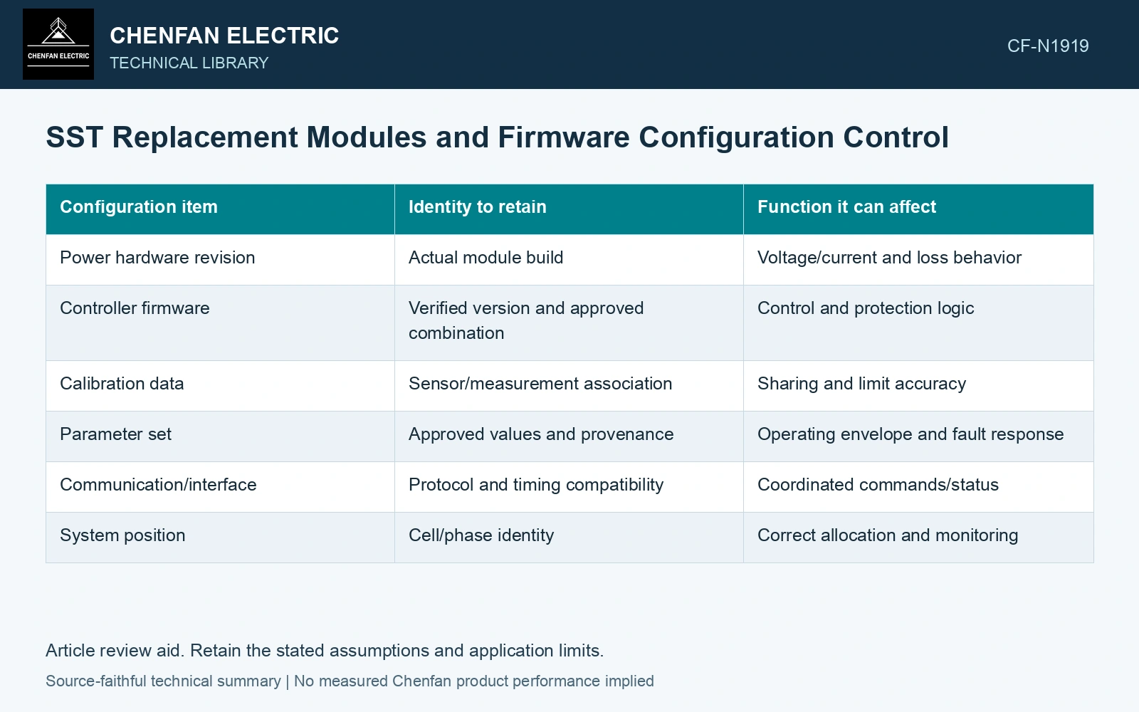
Link the module to the installed system
| Configuration item | Identity to retain | Function it can affect |
|---|---|---|
| Power hardware revision | Actual module build | Voltage/current and loss behavior |
| Controller firmware | Verified version and approved combination | Control and protection logic |
| Calibration data | Sensor/measurement association | Sharing and limit accuracy |
| Parameter set | Approved values and provenance | Operating envelope and fault response |
| Communication/interface | Protocol and timing compatibility | Coordinated commands/status |
| System position | Cell/phase identity | Correct allocation and monitoring |
Preserve old and new identities through the change. A module-position label should agree with both the wiring and the control map.
Review differences before operation
A newer revision is not automatically compatible with every existing combination. The manufacturer should identify approved pairings and any required system-level change. Do not bypass protections or load another module’s data merely to obtain a normal-ready indication.
Equal nominal power does not establish equal dynamic behavior or loss. A balancing controller may compensate for some variation within a qualified range, but that range needs evidence.
Map the affected verification
Check the functions touched by the substitution: sensor identity, voltage/current sharing, startup, port transitions and relevant protection. The scope can be targeted when the difference is understood, rather than repeating unrelated checks or skipping the affected one.
Configuration management ties the released hardware, firmware, parameter set, evidence and approved changes to an identified baseline. For an SST replacement, connect that baseline to the module’s actual conversion-stage functions and interfaces before authorising interchangeability. [1][2]
Preserve the final combination
Record the installed revisions, approved parameter/calibration identities and verification results. If the system is later changed again, the record should show which combination was actually assessed. A generic description such as firmware updated makes that comparison difficult.
Where a component identity remains uncertain, keep the issue open rather than inferring compatibility from successful low-load operation. A narrow operating point cannot establish every limit or fault-state behavior.
The result is a configuration ledger tied to the functions the replacement can change. It protects the meaning of the system’s original qualification and makes later troubleshooting possible. In a modular SST, a spare is fully usable only when its physical and control identities fit the approved system, not merely the empty slot.
References
- NASA, NASA Systems Engineering Handbook, section 6.5, Configuration Management, official online text.
- D.-M. Predescu and Ș.-G. Roșu, Solid State Transformers: A Review—Part I: Stages of Conversion and Topologies, Technologies 13, 74, 2025. DOI: 10.3390/technologies13020074.