

An SST controller’s simulated ride-through covers a defined hardware/model loop. NREL’s PHIL stability study models the full simulator, interface, amplifier and sensor chain [1]. Its solar-inverter case does not qualify an SST’s semiconductors, insulation or fault containment.
Define the loop before interpreting the result. A controller-HIL test and a power-HIL test include different physical boundaries and can support different claims.
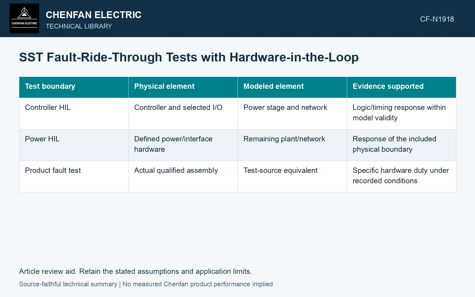
State what is real and what is modeled
| Test boundary | Physical element | Modeled element | Evidence supported |
|---|---|---|---|
| Controller HIL | Controller and selected I/O | Power stage and network | Logic/timing response within model validity |
| Power HIL | Defined power/interface hardware | Remaining plant/network | Response of the included physical boundary |
| Product fault test | Actual qualified assembly | Test-source equivalent | Specific hardware duty under recorded conditions |
The last row is not automatically replaced by either HIL arrangement. Insulation and destructive fault-containment questions may require other qualification evidence.
Validate the model where the fault takes it
A model accurate in normal operation can be unsuitable after switch blocking, saturation or a device fault. Include conductive paths, stored energy, grounding and protection behavior relevant to the event.
Real-time step size and interface delay can alter a fast transient. Preserve those limits and verify that the quantities governing the test are represented adequately. A stable simulation is not evidence of sufficient temporal resolution.
Test a coverage matrix
Identify fault location/type, source condition, load/port state and initial energy. Include valid sensor behavior and credible signal failures. Define the expected permission, limiting or isolation response for each approved case.
Record actual controller outputs and timing as well as simulated electrical quantities. A good-looking simulated voltage can conceal an incorrect hardware command or an interface delay outside the assumed range.
Keep hardware claims proportional
The SST topology review locates conversion and isolation stages [2]. Mark which stages are physically present in the HIL arrangement, then separate control-response evidence from the real device-blocking, stored-energy and insulation duties still needing qualification.
Where power hardware is included, identify scaling, amplifiers and protection that may influence the result. An interface limit can mask or alter the fault duty the original system would see.
For an author’s pure-delay screen, assume unchanged crossover 2 kHz and delay-free phase margin 60°. Interface delays 50/100 μs add lags 36°/72°, leaving 24°/−12°. The second fails this assumed margin screen even with the same SST controller. Characterise the whole test loop as in the PHIL study [1]; crossover shifts and other dynamics need the actual transfer-function assessment. The calculation supplies neither a universal HIL delay limit nor real-product ride-through proof.
The report should name the hardware tested, model validation, case coverage and remaining physical qualification. This allows a purchaser to use HIL evidence for what it actually demonstrates. Passing every modeled case is not the same claim as passing every required product fault or type test, and the documentation should preserve that distinction.
References
- J. Wang, B. Lundstrom, I. Mendoza and A. Pratt, Systematic Characterization of Power Hardware-in-the-Loop Evaluation Platform Stability, NREL/CP-5D00-73162, December 2019, sections II and III.
- D.-M. Predescu and Ș.-G. Roșu, Solid State Transformers: A Review—Part I: Stages of Conversion and Topologies, Technologies 13, 74, 2025. DOI: 10.3390/technologies13020074.