

An SST limits fault current to protect its semiconductors. A downstream fuse may depend on a larger or longer current to clear the same fault. The two protective functions can each operate as designed and still fail to produce the intended system isolation.
The coordination case needs the converter’s fault trajectory and the applicable fuse evidence. Huber and Kolar identify downstream-fuse compatibility as an SST challenge [1]; retain the actual waveform instead of copying a conventional-transformer prospective-current curve.
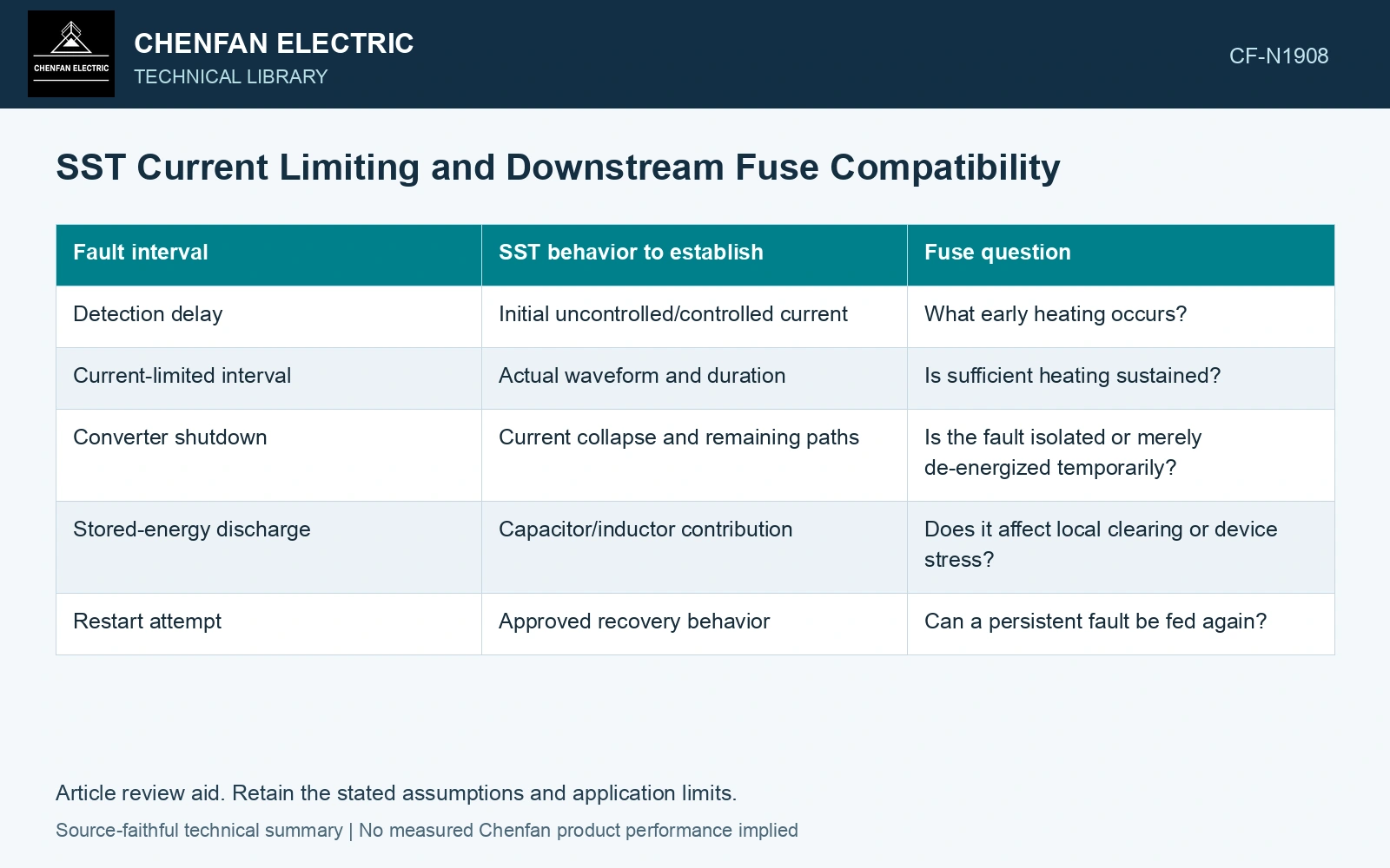
Describe the trajectory, not one limit value
| Fault interval | SST behavior to establish | Fuse question |
|---|---|---|
| Detection delay | Initial uncontrolled/controlled current | What early heating occurs? |
| Current-limited interval | Actual waveform and duration | Is sufficient heating sustained? |
| Converter shutdown | Current collapse and remaining paths | Is the fault isolated or merely de-energized temporarily? |
| Stored-energy discharge | Capacitor/inductor contribution | Does it affect local clearing or device stress? |
| Restart attempt | Approved recovery behavior | Can a persistent fault be fed again? |
Preserve RMS, peak, frequency content and time information appropriate to the analysis. One current limit number cannot establish all of them.
Use I-squared-time with its domain
The integral of current squared over time has units of ampere-squared seconds. It can be relevant to fuse heating under the fuse’s stated conditions. It is not a universal clearing criterion for every waveform, duration and voltage. Heat removal and interruption behavior may matter.
Littelfuse distinguishes melting, arcing and total-clearing I²t [2]. Use the selected fuse’s applicable data at the real voltage and waveform; the guide’s automotive product ratings do not qualify an SST circuit. A melted element alone does not establish successful interruption.
Check selectivity and the remaining fault
If the SST blocks before the fuse operates, determine the final fault boundary. The load circuit may remain physically faulted even though current is temporarily absent. Its restoration needs the approved protection logic, not an assumption that the fuse must have cleared.
If another source or charged link supplies the fault, include that contribution. The fuse and converter can see different currents depending on their locations.
Compare actual evidence at common boundaries
Huber and Kolar identify supplying sufficient fault current for existing downstream fuses as a distribution-SST challenge [1]. Verify the actual limiting waveform across input voltage, port state and fault type before accepting coordination.
Where simplified curves do not represent the waveform, use an appropriate validated model or qualified test. Retain the uncertainty rather than selecting a convenient prospective-current line.
The coordination output should show which device performs final isolation, which parts remain energized and whether the intended selectivity is achieved. Current limiting is useful converter protection. Compatibility with a downstream fuse is a separate system result that must be established from the trajectory both devices actually experience.
References
- J. E. Huber and J. W. Kolar, Solid-State Transformers: On the Origins and Evolution of Key Concepts, IEEE Industrial Electronics Magazine 10(3), 2016. DOI: 10.1109/MIE.2016.2588878.
- Littelfuse, Fuseology, manufacturer technical guide, I²t discussion.