

An SST controller can command switch blocking while output capacitance or another port remains energized. The topology review identifies distinct conversion and isolation paths [1]; determine which physical paths the command actually controls.
Draw the output circuit with every energy source and conductive path included. The fault-blocking claim must state which of them it controls and how the others are contained.
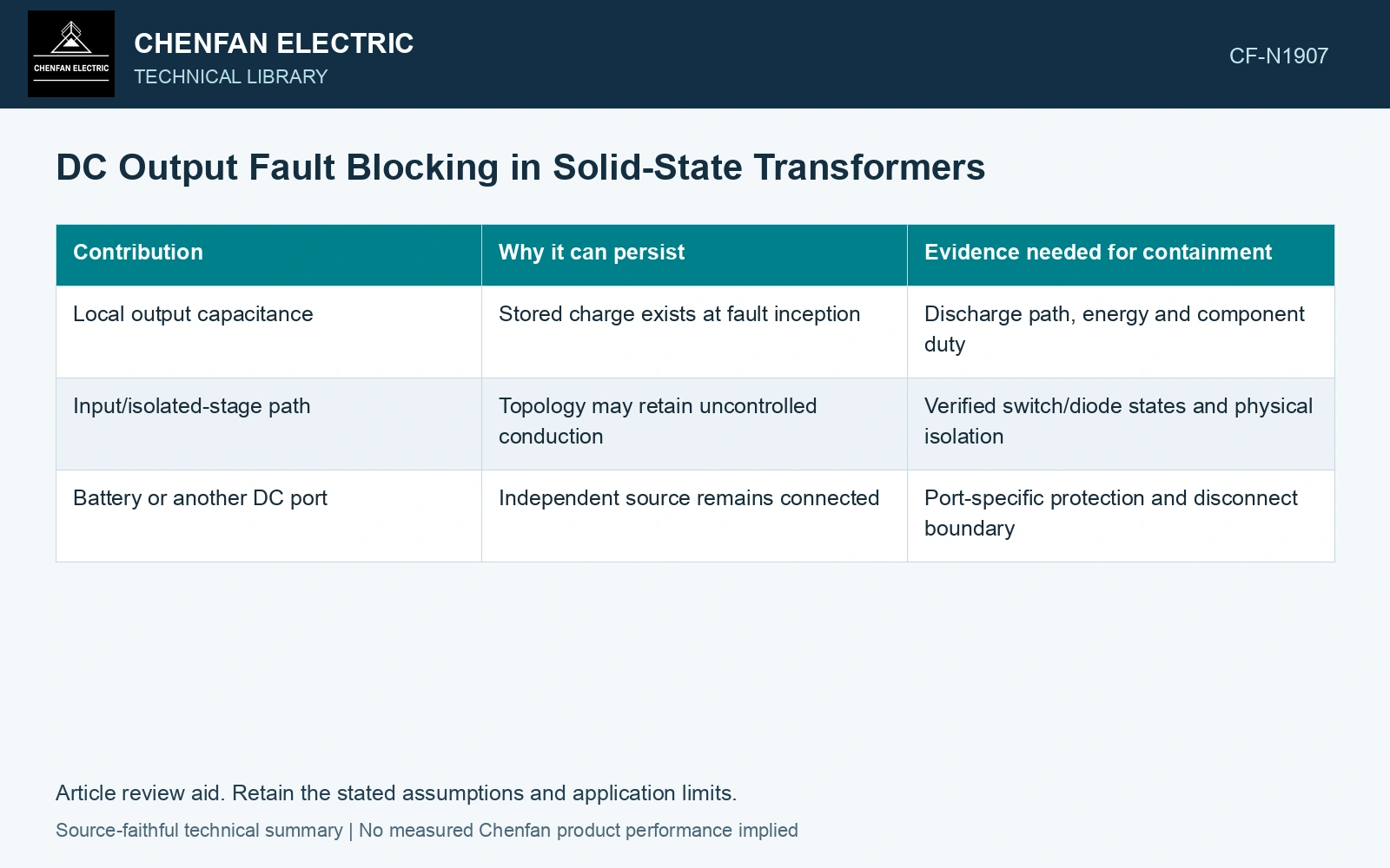
Compare three contributions
| Contribution | Why it can persist | Evidence needed for containment |
|---|---|---|
| Local output capacitance | Stored charge exists at fault inception | Discharge path, energy and component duty |
| Input/isolated-stage path | Topology may retain uncontrolled conduction | Verified switch/diode states and physical isolation |
| Battery or another DC port | Independent source remains connected | Port-specific protection and disconnect boundary |
Galvanic isolation removes a direct conductive connection across its boundary in normal construction. It does not automatically establish zero transferred fault energy while converters operate, nor does it eliminate a charged output-side source.
Quantify stored energy without inventing the peak
For constant ideal capacitance, integrating VdQ with Q=CV [2] gives E=½CV0², in joules. This energy budget does not determine peak fault current: actual resistance, inductance, devices and arc behaviour determine its waveform.
A low energy estimate also does not establish the duty of an individual semiconductor. Energy and current distribution through the actual path need assessment.
Trace the commanded and actual states
Record detection delay, gate commands, device conduction, protective operation and the resulting isolated or limited state. A failed switch can create a different path from the normal blocked-state model. Include the credible failure types covered by the claimed protection.
Trace capacitor discharge and semiconductor/diode conduction in the actual selected topology [1]. Identify the hardware that contains every remaining source and validate its fault duty; a zero gate command cannot isolate a path that it does not control.
Keep port interactions in the case
A multiport system can continue injecting power unless its coordinated controls and hardware establish the accepted boundary. A protection action at one converter does not necessarily disconnect a battery or another source attached to the same DC bus.
If the design limits current rather than interrupts it, identify the sustained state and how it is finally cleared. These are different claims with different component and downstream protection implications.
Assume an 800 V DC output has 2 mF capacitance. Stored energy is 0.5 × 0.002 × 800² = 640 J. Blocking power transfer from the upstream converter does not remove those 640 J or eliminate discharge through an unblocked downstream path. Identify the physical isolation/blocking device and discharge circuit, then validate the fault waveform; a controller flag stating that the isolation stage has stopped is not evidence of zero output fault energy.
The review output should identify each fault source, its path, its energy/current duty and the verified event that contains it. That makes the blocking statement technically precise. It avoids treating a software command as a physical isolation device in a circuit whose remaining paths have never been examined.
References
- D.-M. Predescu and Ș.-G. Roșu, Solid State Transformers: A Review—Part I: Stages of Conversion and Topologies, Technologies 13, 74, 2025. DOI: 10.3390/technologies13020074.
- U.S. Department of Energy, DOE-HDBK-1011/2-92, Electrical Science, Volume 2, 1992.