

A supplier describes an SST as single-stage. Another describes three stages. The labels do not establish which unit can regulate an output, connect a battery or decouple input and output frequency. Those functions follow the circuit and controls, not the shortest description.
Trace power from each input to each output. Identify where isolation occurs, where energy can be stored and which conversion stages can independently control a quantity.
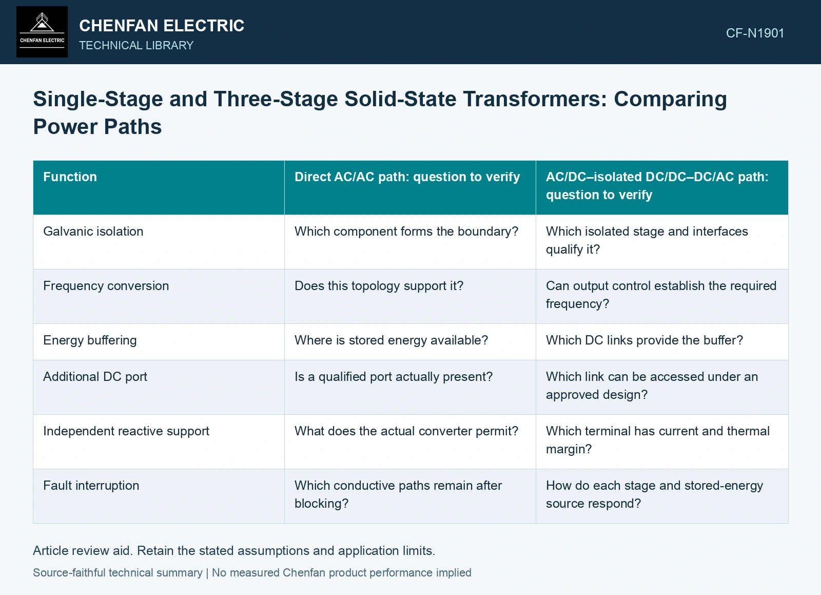
Compare functions along the path
A common three-stage AC/AC arrangement includes an input AC/DC stage, an isolated DC/DC stage and an output DC/AC stage. A direct isolated AC/AC arrangement may be called single-stage under another classification. Real families have variations, so confirm what the stage count includes.
| Function | Direct AC/AC path: question to verify | AC/DC–isolated DC/DC–DC/AC path: question to verify |
|---|---|---|
| Galvanic isolation | Which component forms the boundary? | Which isolated stage and interfaces qualify it? |
| Frequency conversion | Does this topology support it? | Can output control establish the required frequency? |
| Energy buffering | Where is stored energy available? | Which DC links provide the buffer? |
| Additional DC port | Is a qualified port actually present? | Which link can be accessed under an approved design? |
| Independent reactive support | What does the actual converter permit? | Which terminal has current and thermal margin? |
| Fault interruption | Which conductive paths remain after blocking? | How do each stage and stored-energy source respond? |
The matrix asks for evidence. It does not grant every listed function to either architecture.
Locate the coupled controls
An intermediate DC link can decouple some instantaneous power behavior, but its voltage must remain within its accepted range. The isolated stage and endpoint converters still share an energy balance. A diagram with three control blocks does not establish unlimited independence.
Conversely, fewer stages can reduce some conversion interfaces while coupling functions that another architecture controls separately. Evaluate whether that coupling matters to the intended service.
Compare complete boundaries
The conversion-stage review classifies SST architectures by their physical paths and available functions. Compare the same input/output service, isolation and control requirements before treating stage count as an efficiency or equipment ranking. [1][2]
For a fictional equal-service comparison, assume single-stage efficiency 97.5% and three-stage efficiencies 99%/98%/99% at the evaluated ports/duty. The product is 96.0498%, before any separately excluded auxiliaries; 100 kW output needs 102.56/104.11 kW input. Compare the same isolation, ports, control authority and operating range before choosing the lower conversion loss. These are assumptions, not measurements or efficiencies supplied by either review.
For procurement, state the required ports, isolation, control behavior and fault duties first. Then compare architectures that provide the same service. That produces a meaningful technical decision. Choosing the fewest stages without a function map can remove a capability that the application actually needs.
References
- J. E. Huber and J. W. Kolar, Solid-State Transformers: On the Origins and Evolution of Key Concepts, IEEE Industrial Electronics Magazine 10(3), 2016. DOI: 10.1109/MIE.2016.2588878.
- D.-M. Predescu and Ș.-G. Roșu, Solid State Transformers: A Review—Part I: Stages of Conversion and Topologies, Technologies 13, 74, 2025. DOI: 10.3390/technologies13020074.