

An open-transition transfer disconnects one source before the load receives the other. A closed-transition transfer creates a period in which both sources are connected. That distinction changes the circuit being assessed, even if the final source and load arrangement is identical. [1]
The review should model the actual electrical timeline. It should not infer temporary paralleling permission from a successful long-term transformer load calculation.
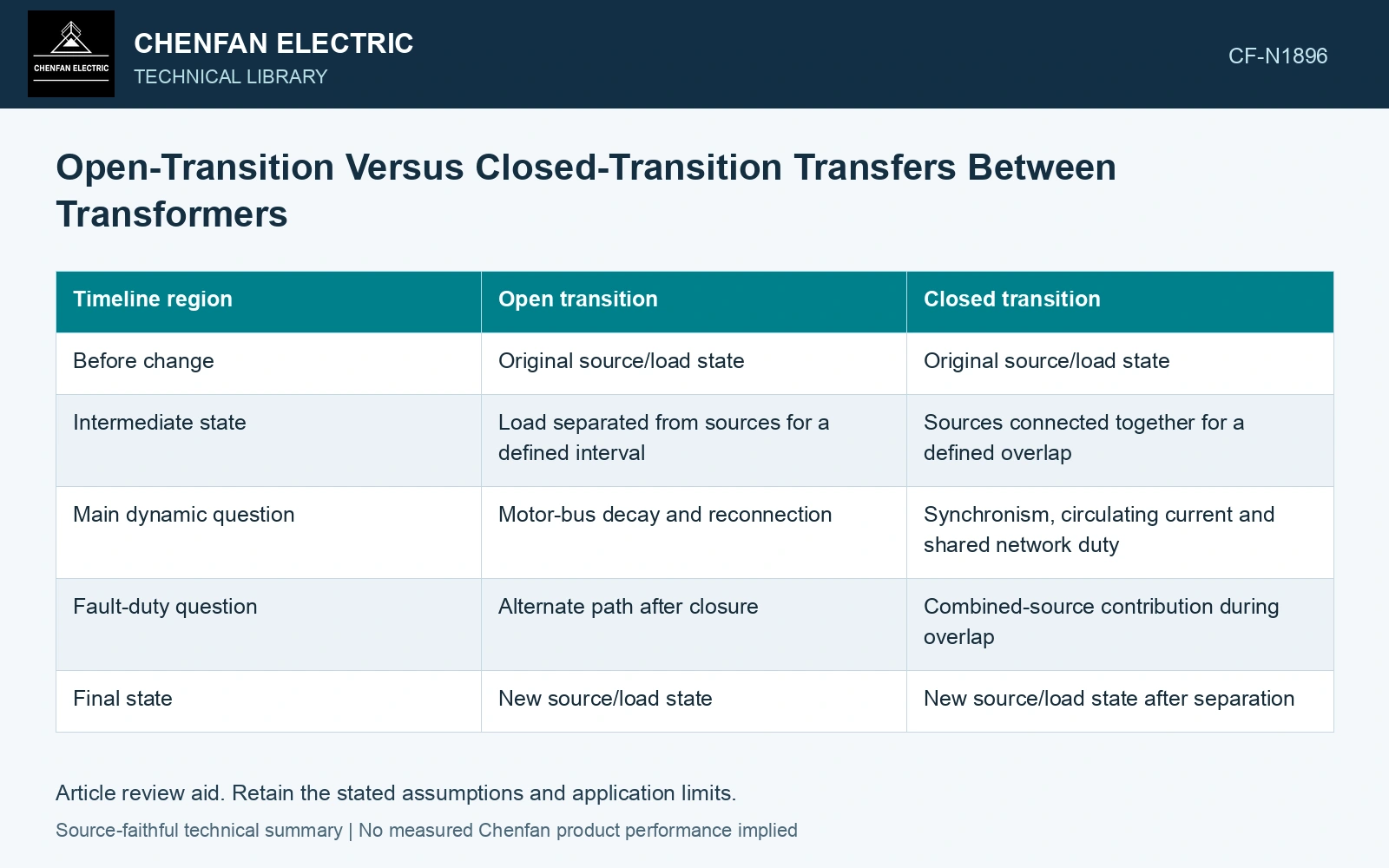
Compare the intermediate circuits
| Timeline region | Open transition | Closed transition |
|---|---|---|
| Before change | Original source/load state | Original source/load state |
| Intermediate state | Load separated from sources for a defined interval | Sources connected together for a defined overlap |
| Main dynamic question | Motor-bus decay and reconnection | Synchronism, circulating current and shared network duty |
| Fault-duty question | Alternate path after closure | Combined-source contribution during overlap |
| Final state | New source/load state | New source/load state after separation |
This comparison supplies no switching sequence or time value. The permitted timeline comes from the approved design.
Examine the overlap current
Under a simplified steady sinusoidal equivalent, a voltage-vector difference ΔV between two sources drives a circulating component approximately ΔV/Zloop. ΔV is in volts and loop impedance Zloop in ohms, giving current in amperes. The expression assumes a suitable linear equivalent and ignores switching transients.
Small magnitude or angle differences can therefore matter if loop impedance is small. The actual case needs source, transformer, cable and connection data, along with the dynamic closure state. Equal nominal voltage does not establish zero difference.
Review protection during the temporary state
A brief overlap can alter fault contribution and relay measurement boundaries. Existing interrupting and protection assumptions need to cover that circuit even if it exists only briefly. A short duration does not eliminate the possibility of a fault occurring within it.
Open transition has another requirement: the disconnected load’s state evolves. Motors may slow, contactors release and drives trip. The resulting reconnection case cannot be modeled as an undisturbed load merely because the gap is intended to be small.
The overlap calculation needs phasor voltage and complex loop impedance at the same frequency. Retain their common reference rather than mixing RMS magnitudes with an angle comparison. [2]
Estimate the overlap circulation
Assume a 400 V RMS per-phase comparison with a 10 V source-vector difference and a 0.10 Ω loop impedance. The simplified circulating component is 10/0.10 = 100 A RMS. Doubling the difference gives 200 A, before load current is added. This screen justifies checking the overlap network; it does not authorize paralleling.
Verify departure from the intermediate state
A delayed or failed device operation can extend the gap or overlap beyond the intended case. Include credible failure states and the approved logic’s response. A successful command is not proof that the electrical boundary changed at the expected time.
References
- P. Muralimanohar, D. Haas, J. R. McClanahan, R. T. Jagaduri and S. Singletary, Implementation of a Microprocessor-Based Motor Bus Transfer Scheme, IEEE PCIC, 2016, DOI: 10.1109/PCICON.2016.7589248.
- U.S. Department of Energy, DOE-HDBK-1011/3-92, Electrical Science, Volume 3, June 1992.