

One VT fuse fails and the relay sees a low voltage. The power circuit may still be healthy. If that reading initiates transfer or makes the bus appear dead, a measurement failure can be mistaken for an electrical event. [1]
The scheme needs a validity assessment for the voltage signals used in source-loss detection and synchronism. This is separate from whether the VT normally meets its accuracy requirement.
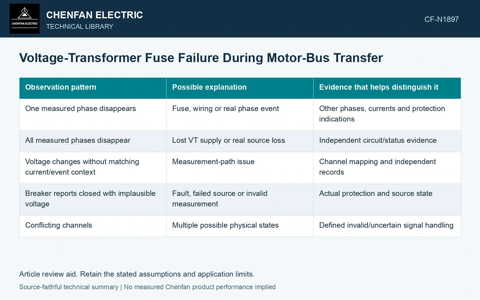
Compare independent evidence
| Observation pattern | Possible explanation | Evidence that helps distinguish it |
|---|---|---|
| One measured phase disappears | Fuse, wiring or real phase event | Other phases, currents and protection indications |
| All measured phases disappear | Lost VT supply or real source loss | Independent circuit/status evidence |
| Voltage changes without matching current/event context | Measurement-path issue | Channel mapping and independent records |
| Breaker reports closed with implausible voltage | Fault, failed source or invalid measurement | Actual protection and source state |
| Conflicting channels | Multiple possible physical states | Defined invalid/uncertain signal handling |
No single row is a universal diagnosis. A real fault can produce patterns that resemble measurement failure. The algorithm’s conclusion needs verification over the actual network cases.
Trace the measurement supply
Identify primary and secondary protection, wiring, sensor type and the source of any auxiliary measurement electronics. The voltage path can fail independently of the power path. Mark which relay channels share one vulnerable component so that supposedly independent evidence is not duplicated.
A common upstream fuse or supply can remove several channels together. Three absent readings are therefore not automatically three independent confirmations of source loss.
Protect the comparison when validity is lost
If the voltage relationship is invalid, the relay cannot make a normal phase comparison on that evidence. The approved scheme must define how it handles the uncertain state. Retaining the last valid phasor indefinitely is not a physically current observation.
VT/PT fuses, wiring and relay-input failures can remove measurement voltage without removing power-circuit voltage; voltage-dependent functions need verified loss-of-potential supervision. [2]
Challenge the invalid-voltage state
For an assumed offline test matrix, one phase reports zero while the other two remain at their nominal scaled values and the independent breaker status remains closed. Repeat with all voltage channels lost. The expected result must come from approved signal-validity logic: multiple channels sharing one fuse are one failure path, rather than independent evidence of a dead bus.
Test failure timing as well as failure pattern
A fuse can fail before the event, during decay or while an alternate-source comparison is underway. These times can affect different logic states. Verification should exercise the actual approved algorithm with valid and invalid waveforms, status inputs and communication conditions.
References
- P. Muralimanohar, D. Haas, J. R. McClanahan, R. T. Jagaduri and S. Singletary, Implementation of a Microprocessor-Based Motor Bus Transfer Scheme, IEEE PCIC, 2016, DOI: 10.1109/PCICON.2016.7589248.
- S. R. Sathu, D. Finney, S. Samineni and D. J. Hawaz, Loss-of-Potential Detection for Generator Relays, Schweitzer Engineering Laboratories, Georgia Tech Protective Relaying Conference, April 2024.