

A bus coupler changes which network a neutral grounding connection serves. If neutral switches are also involved, the design can briefly create overlapping grounding paths or leave a connected bus without its intended ground reference. The review needs a complete state map, including abnormal feedback. [1]
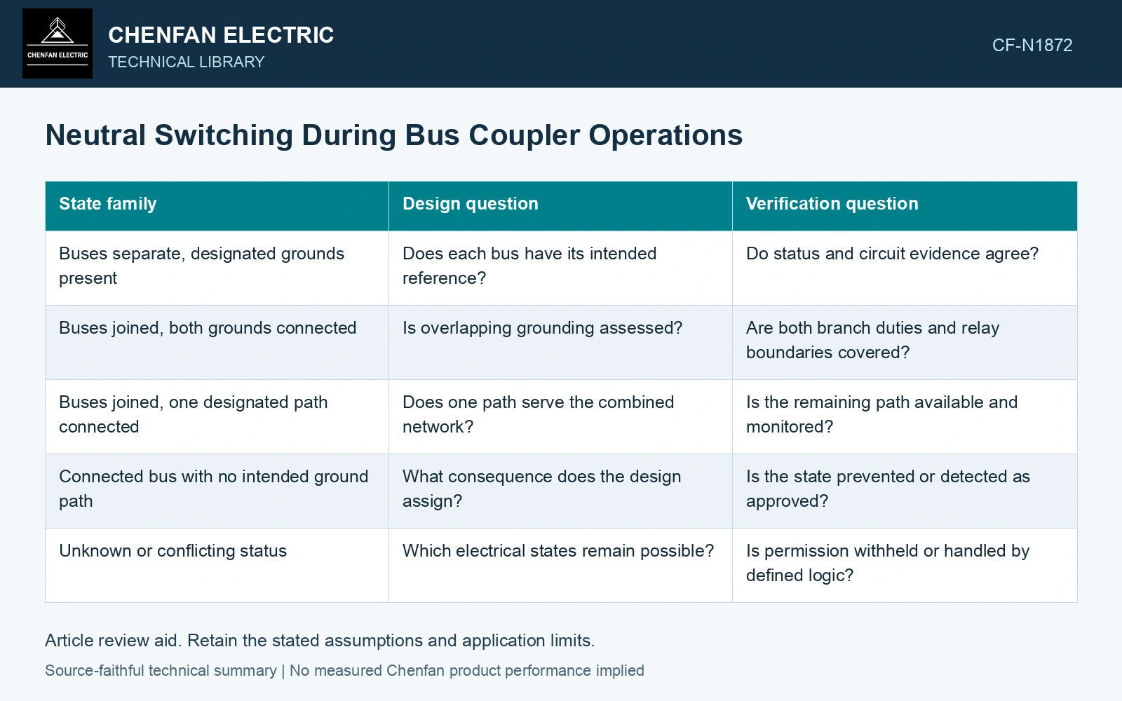
The matrix below is a way to analyze the design. It does not specify the order in which switches should be operated. Actual switching instructions belong to the approved station procedure.
Name electrical states, not just device labels
For each coupler and neutral-switch combination, identify which bus sections are connected and which grounding paths exist. Mark states that the engineering design permits, rejects or treats as conditional. The categories must come from the actual system study.
| State family | Design question | Verification question |
|---|---|---|
| Buses separate, designated grounds present | Does each bus have its intended reference? | Do status and circuit evidence agree? |
| Buses joined, both grounds connected | Is overlapping grounding assessed? | Are both branch duties and relay boundaries covered? |
| Buses joined, one designated path connected | Does one path serve the combined network? | Is the remaining path available and monitored? |
| Connected bus with no intended ground path | What consequence does the design assign? | Is the state prevented or detected as approved? |
| Unknown or conflicting status | Which electrical states remain possible? | Is permission withheld or handled by defined logic? |
Examine the intervals between accepted states
Two acceptable final states do not prove that the transition between them is acceptable. Device delays and status timing can create an interval that the steady-state study never examined. Assess that interval’s grounding network and protection visibility.
A contact indication is evidence of a reported device position. It may not independently prove continuity of the neutral path. Keep monitor information, auxiliary contacts and mechanical status within their actual coverage limits.
Test interlock failures deliberately
The design review should consider stuck indications, lost control power, delayed device operation and a grounding monitor alarm. Identify how each changes the permission logic. A test that checks only normal contact combinations misses the state in which a command succeeds but feedback does not arrive.
The cited system case shows that removing the only effective grounding source can leave an energized network without that reference. [2] Apply that topology check to each coupler/neutral-switch intermediate state, including delayed and conflicting feedback.
Identify the overlap in the state record
Assume neutral path A opens at 150 ms while path B closes at 110 ms. The grounding paths overlap for 40 ms. Reversing those times creates a 40 ms gap instead. Assess each intermediate circuit and feedback failure; neither duration is a recommended operating sequence.
References
- IEEE, IEEE C57.32-2015, IEEE Standard for Requirements, Terminology, and Test Procedures for Neutral Grounding Devices (historical edition).
- D. De Ronde, R. VanHatten and A. Wade, Loss of Effective System Grounding — Best Practices, Protection Challenges, and Solutions, Schweitzer Engineering Laboratories, 2015.