

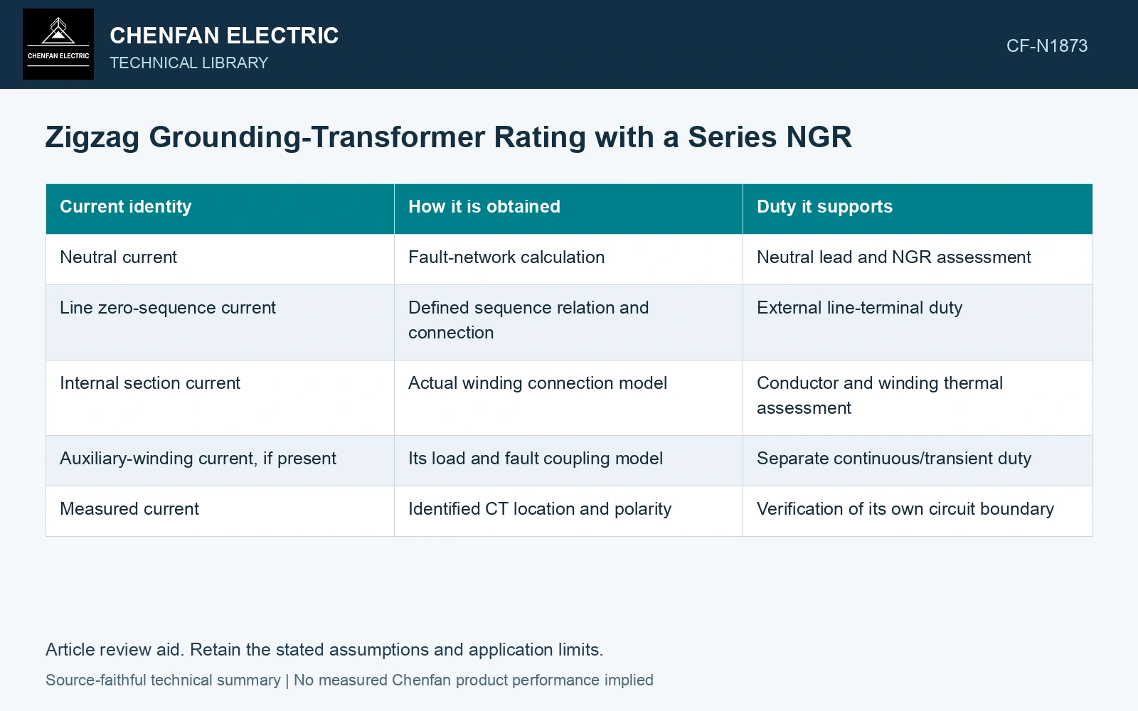
Rate the zigzag grounding transformer and its series NGR on one fault network. The NGR carries neutral current; each identified zigzag line path carries its own winding current. IEC 60076-6 includes earthing transformers, while the connection determines how their coils carry zero-sequence duty. [1]
State the winding and impedance boundaries
In an ideal balanced zero-sequence case, IN = 3I₀. The zigzag construction uses cross-phase coils with opposing zero-sequence ampere-turns on a limb. [2] For this example assume each line path contains two series half-coils, so each half-coil carries that line’s I₀. Keep any auxiliary winding and pre-fault heating separate in the actual assembly map.
Let Z₀ be the grounding transformer’s zero-sequence impedance per phase, referred to the connected bus, and Rn the neutral resistor. With a stiff balanced source, a solid earth fault, one grounding source and all other source/sequence impedances neglected, IN = Vph/(Rn + Z₀/3). Use complex impedance at the same frequency and reference. [3] The factor of three belongs to the chosen line/neutral relationship; it must not be dropped when referring Z₀ into the neutral branch.
Check the resistor and the half-coils on one assumed event
Assumptions: 6.6 kV line-to-line at 50 Hz; Rn = 100 Ω, constant during the event; Z₀ = j150 Ω per phase; fault duration 10 s; no auxiliary load. Then Vph = 6,600/√3 = 3,810.5 V RMS, and the neutral branch sees 100 + j50 Ω. Its current is 34.082 A RMS; the line and each specified half-coil carry 11.361 A RMS.
The NGR absorbs IN²Rn = 116.16 kW and 1.1616 MJ over the event. Assume a hypothetical resistor assembly is qualified for 120 kW for 10 s at the specified starting condition: this electrical input lies within that rating. Its actual hot resistance, supports and repeat duty still belong to the supplier’s qualification record.
Now assume each half-coil’s existing qualification covers only 10 A for 10 s at the same initial condition. The requested I²t is 11.361² × 10 = 1,290.7 A²s, versus 1,000 A²s in that record, 29.1% higher. The NGR passing its own input check does not release the winding. Reject this combined assembly duty until the transformer is re-rated or directly supported for the specified event.
Keep a resistance-only approximation visible
Ignoring Z₀ gives 38.105 A neutral current and 145.20 kW in the resistor, instead of 34.082 A and 116.16 kW. The actual transformer impedance therefore changes both the fault current and the apparent component margin. Use its measured or justified value rather than switching silently between the two models.
Issue the same voltage, current waveform, duration, initial temperature and repetition schedule to both suppliers. Require their records to identify neutral leads, each coil section, resistor elements and supports. Add auxiliary-load preheating and cooling degradation where those states can precede the fault; the numerical example covers only its stated single-event configuration.
References
- IEC, IEC 60076-6:2007, Power transformers — Part 6: Reactors.
- D. De Ronde, R. VanHatten and A. Wade, Loss of Effective System Grounding — Best Practices, Protection Challenges, and Solutions, Schweitzer Engineering Laboratories, 2015.
- U.S. Department of Energy, DOE-HDBK-1011/3-92, Electrical Science, Volume 3, June 1992.