

An intact resistor bank does not guarantee an intact neutral-grounding path. The neutral lead can open, an earth connection can fail or a monitoring component can become disconnected. Open-NGR detection should therefore be assessed as coverage of a circuit boundary. [1]
A product description saying resistor monitored is incomplete. Ask which path the monitor observes and which failures can produce an alarm under normal and fault conditions. The answer depends on the specific sensing arrangement.
Define the observed path
Some systems use an injected monitoring signal or a sensing network to infer continuity. The intended signal can travel through only part of the grounding path or through an unintended parallel route. Do not assume that the monitor’s normal indication proves every series component is connected.
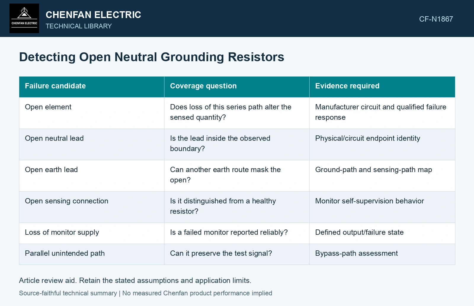
| Failure candidate | Coverage question | Evidence required |
|---|---|---|
| Open element | Does loss of this series path alter the sensed quantity? | Manufacturer circuit and qualified failure response |
| Open neutral lead | Is the lead inside the observed boundary? | Physical/circuit endpoint identity |
| Open earth lead | Can another earth route mask the open? | Ground-path and sensing-path map |
| Open sensing connection | Is it distinguished from a healthy resistor? | Monitor self-supervision behavior |
| Loss of monitor supply | Is a failed monitor reported reliably? | Defined output/failure state |
| Parallel unintended path | Can it preserve the test signal? | Bypass-path assessment |
Test coverage, not just an alarm lamp
A qualified verification plan can map each credible failure to the expected indication and available blocking or protection response. The plan belongs to the responsible specialist and equipment design; this matrix is not a field-disconnection procedure.
Include the ground-fault condition
The monitor sees a different electrical environment during a power-frequency fault. Its behavior, isolation and protection need to remain suitable, or a defined temporary loss of supervision must be handled by the approved system logic. A normal-state signal result cannot establish fault-state endurance.
Record whether the alarm identifies an open path, a monitoring fault or merely an out-of-range condition. Those meanings affect the subsequent investigation. A common alarm can be acceptable only when its scope and required response are clear.
The monitor observes its own AC or injected-signal network, including any parallel impedance. [2] Map the frequency-dependent path separately from the intended neutral-to-earth power-frequency resistor path when proving open-path coverage.
Demonstrate the parallel-path blind spot
Assume the intended 100 Ω resistor path opens while a separate 10 kΩ monitoring-frequency path remains. A detector that only checks finite impedance can still see continuity. Specify its valid impedance window and observed endpoints, then verify the applicable open-path cases through the approved test method. A lamp test cannot establish that coverage.
References
- IEEE, IEEE C57.32-2015, IEEE Standard for Requirements, Terminology, and Test Procedures for Neutral Grounding Devices (historical edition).
- U.S. Department of Energy, DOE-HDBK-1011/3-92, Electrical Science, Volume 3, June 1992.