

When load moves from one transformer feeder to another, the receiving cable does not begin at a blank thermal state. It may already be carrying a high load in warm ground. The emergency rating must begin at that condition and follow the transferred duty through time. [1]
A spare transformer capacity figure cannot establish cable capacity. The conductor, joints, terminations, screens and local route sections need their own assessed limits. A temporary duty can be acceptable for one component while another governs earlier.
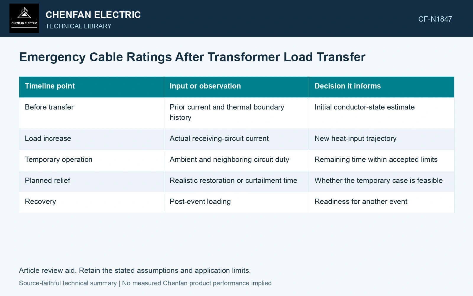
Put the transfer on a thermal timeline
Record the loading history available before the event, the moment the receiving cable’s duty changes and the expected relief action. Include uncertainty in both initial temperature and transferred load. If actual load differs from the forecast, the temperature trajectory needs to be updated.
| Timeline point | Input or observation | Decision it informs |
|---|---|---|
| Before transfer | Prior current and thermal boundary history | Initial conductor-state estimate |
| Load increase | Actual receiving-circuit current | New heat-input trajectory |
| Temporary operation | Ambient and neighboring circuit duty | Remaining time within accepted limits |
| Planned relief | Realistic restoration or curtailment time | Whether the temporary case is feasible |
| Recovery | Post-event loading | Readiness for another event |
Headroom is a state, not a fixed multiplier
The physical balance is stored-heat change equals heat generation minus heat removal. In a simplified lumped model, Cth dθ/dt = P − (θ − θa)/Rth. Cth is thermal capacitance in joules per kelvin, θ and θa are temperatures in degrees Celsius, P is heat generation in watts and Rth is thermal resistance in kelvins per watt.
This illustrative model explains why hotter initial conditions reduce time margin. It does not capture a full cable’s distributed thermal network, and it cannot justify a universal overload percentage. The proper assessment needs the cable construction, route and accepted temperature/duty criteria.
Check the limiting location
A short duct entry or joint bay may govern even if the long buried section remains cooler. Use route-specific conditions and the relevant component evidence. The emergency trajectory should identify where and when the first accepted limit is reached.
The stored-energy balance retains the initial thermal state. A constant-loss step approaches its new steady temperature exponentially in a linear one-node approximation; a complete cable rating must retain the relevant distributed heat capacities. [2]
Carry the pre-transfer thermal state
Assumptions: a conductor thermal node has time constant 4 h, a new steady rise of 70 K and surrounding temperature 25 °C. The accepted conductor gate is 90 °C, so the rise gate is 65 K. For an initial rise of 40 K, x(t) = 70 − 30e⁻ᵗ/⁴ reaches 65 K after 4ln(30/5) = 7.17 h. Starting at 60 K gives x(t) = 70 − 10e⁻ᵗ/⁴ and only 4ln(10/5) = 2.77 h. A planned 4 h transfer predicts 83.96 °C in the cooler case and 91.32 °C in the hotter case. Accept the planned duration only in the cooler modeled state; arrange earlier relief for the hotter state and qualify all route/accessory limits before operation. [1][2]
References
- IEC, IEC 60853-2:1989, Calculation of the cyclic and emergency current rating of cables — Part 2: Cyclic rating of cables greater than 18/30 (36) kV and emergency ratings for cables of all voltages.
- U.S. Department of Energy, DOE-HDBK-1012/2-92, Thermodynamics, Heat Transfer, and Fluid Flow, Volume 2, 1992.