

A post-repair result differs from the pre-fault report. Before treating that difference as a defect, establish whether both measurements describe the same quantity under comparable conditions. The old report may use another tap, temperature, connection or interpretation method. [1]
The opposite mistake is equally serious: dismissing every difference as a test-method issue. A useful comparison identifies which conditions are aligned, which can be corrected credibly and which leave the engineering conclusion unresolved.
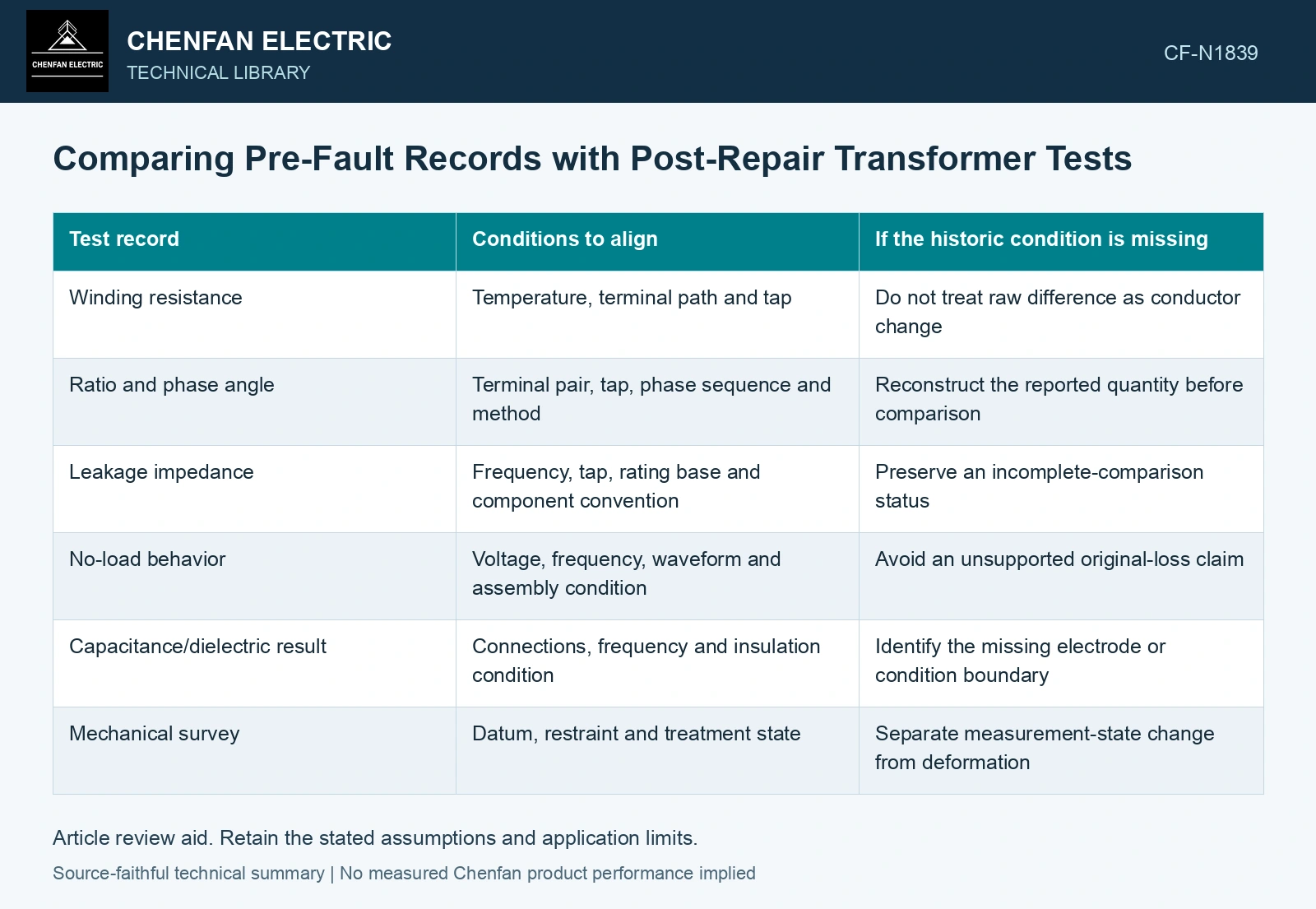
Build the common basis by test
| Test record | Conditions to align | If the historic condition is missing |
|---|---|---|
| Winding resistance | Temperature, terminal path and tap | Do not treat raw difference as conductor change |
| Ratio and phase angle | Terminal pair, tap, phase sequence and method | Reconstruct the reported quantity before comparison |
| Leakage impedance | Frequency, tap, rating base and component convention | Preserve an incomplete-comparison status |
| No-load behavior | Voltage, frequency, waveform and assembly condition | Avoid an unsupported original-loss claim |
| Capacitance/dielectric result | Connections, frequency and insulation condition | Identify the missing electrode or condition boundary |
| Mechanical survey | Datum, restraint and treatment state | Separate measurement-state change from deformation |
Keep raw data and interpreted values together
Retain the raw terminal readings or instrument report where available. A software-generated percentage or vector-group label may depend on configuration entries that were not printed. Recalculation can be useful only when the inputs and interpretation are known.
Record any transformation applied to make results comparable. State the model, its assumptions and the original value. A temperature correction, for example, is not a license to alter an unknown conductor material or combine different terminal paths into one number.
Investigate patterns across the repaired assembly
A phase-specific difference can help focus an investigation, especially when one phase was rewound. A tap-specific difference can identify a regulating-path question. These patterns are clues that need a circuit or construction explanation, not automatic fault classifications.
Compare the observed pattern with the repair-change register. A new lead route might explain a local geometry difference but not a changed turns schedule. A conductor substitution might affect resistance while leaving the induced-voltage ratio unchanged. The explanation should match the quantity that changed.
A resistance comparison must include the uncertainty after temperature correction, including temperature and material-constant contributions where relevant. Propagate both records into the corrected difference rather than judging their raw displayed digits. [2]
Normalize resistance on a declared basis
Assumptions: an identified copper winding reads 1.00 Ω at 20 °C; the post-repair result is 1.220 Ω on the same terminal/tap basis at 75 °C. FIST 3-31 gives the copper correction constant 234.5 °C [1]. Correcting the earlier reading gives 1.00(234.5 + 75)/(234.5 + 20) = 1.216110 Ω, so the corrected increase is 0.003890 Ω. Assume each final corrected result has independent standard uncertainty 0.001 Ω, inclusive of temperature correction. Then uΔ = √(0.001² + 0.001²) = 0.001414 Ω. With assumed coverage factor 2, the difference interval is 0.001062–0.006718 Ω and excludes zero. Investigate this resolved increase against the repair change register before release; the raw 22% difference would have confused temperature with a conductor change. [2]
References
- U.S. Bureau of Reclamation, FIST Volume 3-31, Transformer Diagnostics, June 2003, section 15.1.
- B. N. Taylor and C. E. Kuyatt, NIST Technical Note 1297, Guidelines for Evaluating and Expressing the Uncertainty of NIST Measurement Results, 1994, sections 5 and 6.