

The new bushing matches the voltage and current ratings and its flange appears to fit. Those checks do not settle its compatibility with the turret. The lower end may place the internal conductor differently, change an insulation boundary or impose a new bending load on the retained structure. [1]
A retrofit review should draw the bushing and turret as one interface. Include the internal lead connection, tank or gas boundary, field-control components and external terminal loading. Record the old geometry before removing it so that a hidden difference can be identified later.
Follow the interface below the flange
The flange plane is a useful datum, but it is not the only one. Compare lower-end length, conductor position, connection geometry, nearby grounded surfaces and insulation clearances. The new bushing’s internal construction may require different surrounding field control even if its visible porcelain or composite housing looks similar.
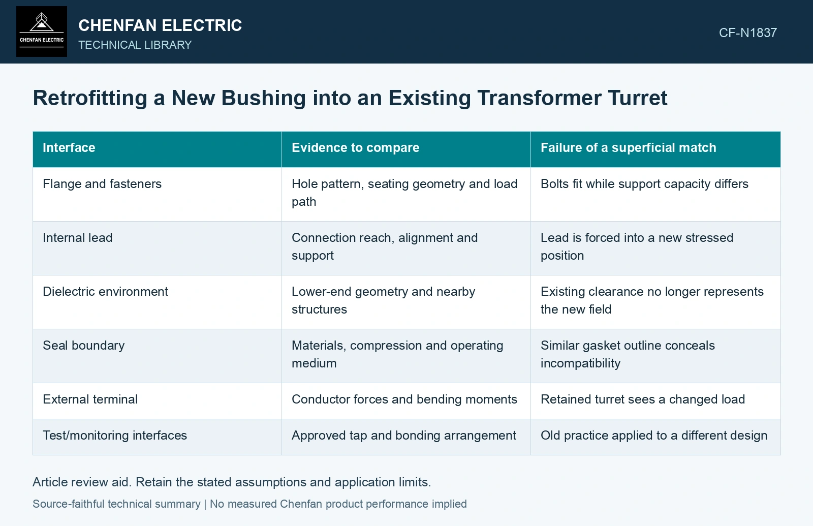
| Interface | Evidence to compare | Failure of a superficial match |
|---|---|---|
| Flange and fasteners | Hole pattern, seating geometry and load path | Bolts fit while support capacity differs |
| Internal lead | Connection reach, alignment and support | Lead is forced into a new stressed position |
| Dielectric environment | Lower-end geometry and nearby structures | Existing clearance no longer represents the new field |
| Seal boundary | Materials, compression and operating medium | Similar gasket outline conceals incompatibility |
| External terminal | Conductor forces and bending moments | Retained turret sees a changed load |
| Test/monitoring interfaces | Approved tap and bonding arrangement | Old practice applied to a different design |
Keep three load systems separate
Electrical current creates losses at the bushing and its joint. Mechanical terminal forces pass through the bushing, flange and turret. Pressure and temperature act on the sealed boundary. A favorable result in one system does not establish compatibility in the others.
If an adapter is introduced, include it in every relevant assessment. It can shift the bushing elevation, change stiffness or create another sealing plane. A plate that resolves the bolt pattern is therefore a new structural and dielectric interface, not merely a workshop convenience.
For an adapter or changed flange load path, qualify the bolted joint’s preload and stiffness with the actual fastener, contact and friction conditions. A nominal torque or matching bolt circle alone does not establish the retained structure’s load capability. [2]
Test the replacement lower-end envelope
Assumptions: the retained turret offers 420 mm below the flange to the controlling interface, the replacement lower-end envelope is 390 mm, and the approved retrofit requires 35 mm geometric allowance. Available allowance is 420 − 390 = 30 mm, 5 mm short. Reject this dimensional fit and revise the replacement/adapter interface before installation. The assumed 35 mm is a project envelope allowance; actual dielectric field, lead motion, mechanical loading and sealing still require the rebuilt assembly’s qualification. [1]
Check the surrounding assembly after installation
The final lead route should be compared with the approved geometry. An internal conductor that can reach the terminal may still have insufficient support or an unfavorable bend. Verify the interfaces disturbed during installation, including nearby barriers and shields.
References
- IEC, IEC 60137:2017, Insulated bushings for alternating voltages above 1000 V.
- R. T. Barrett, Fastener Design Manual, NASA Reference Publication 1228, 1990.