

A transformer can recover its turns ratio after repair and show a different measured capacitance. That result is not necessarily contradictory. Ratio concerns induced voltage relationships, while capacitance depends on conductor geometry, dielectric properties and the electrical boundary used for measurement. [1]
The first step is to list what changed: winding position, barriers, lead routes, shields, support materials or grounding connections. Preserve those changes as candidate mechanisms before deciding that the measured difference proves damage.
Draw the electrodes the test actually sees
A label such as winding-to-ground capacitance can conceal several connected structures. Identify which winding terminals are joined, which other windings are included or excluded and which screens, core or clamps remain connected to the reference. A changed test boundary can mimic a geometric change.
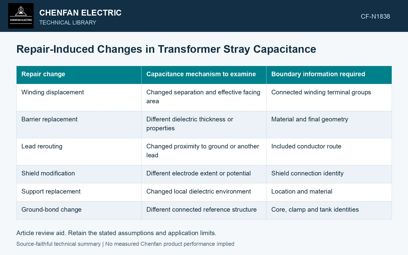
| Repair change | Capacitance mechanism to examine | Boundary information required |
|---|---|---|
| Winding displacement | Changed separation and effective facing area | Connected winding terminal groups |
| Barrier replacement | Different dielectric thickness or properties | Material and final geometry |
| Lead rerouting | Changed proximity to ground or another lead | Included conductor route |
| Shield modification | Different electrode extent or potential | Shield connection identity |
| Support replacement | Changed local dielectric environment | Location and material |
| Ground-bond change | Different connected reference structure | Core, clamp and tank identities |
Use simple equations only as sensitivity tools
For ideal parallel plates, C = εA/d. C is capacitance in farads, ε is permittivity in farads per metre, A is facing area in square metres and d is separation in metres. This model assumes uniform geometry and field, and neglects fringing. A transformer is not a stack of independent ideal plates.
The equation still explains why separation, material and facing area deserve attention. If a modeled local gap increases while other terms remain fixed, that ideal local capacitance decreases. It does not follow that the terminal measurement changes by the same proportion, because many distributed elements contribute to the measured network.
Compare before-and-after conditions
Align test connections, frequency, temperature and relevant insulation condition where possible. Record the instrument and the actual reported quantity. A single number copied from a historical report without its connections is a weak baseline for a repaired assembly.
Where several changes occurred together, avoid assigning the full difference to the most visible one. A moved coil and a revised shield can act in different directions. Use a geometry model or targeted comparisons to determine whether the observed result is consistent with the rebuilt arrangement.
For contributions connected across the same two electrode potentials, parallel capacitances add. A changed shield connection can alter that network topology, so preserve the actual AC measurement boundary before applying a local gap model. [2]
Separate local and terminal capacitance change
Assumptions: an ideal 100 pF local gap is in parallel with a fixed 400 pF contribution. Increasing only that gap by 10% gives 100/1.1 = 90.91 pF locally and 490.91 pF at the terminals, 1.82% below the original 500 pF. Suppose the rebuilt assembly instead measures 470 pF under the same connections and the project model-agreement gate is ±10 pF, inclusive of its accepted uncertainty allowance. The residual 470 − 490.91 = −20.91 pF exceeds that gate by 10.91 pF. Hold the geometric explanation and check electrode/shield connections, material and other changed gaps; do not attribute the entire shift to this one barrier. [2]
References
- U.S. Bureau of Reclamation, FIST Volume 3-31, Transformer Diagnostics, June 2003.
- U.S. Department of Energy, DOE-HDBK-1011/3-92, Electrical Science, Volume 3, June 1992.