

In a thin tank weld, a pulse can return from the backwall quickly while the instrument is still resolving the initial response or another echo. Joint geometry adds further reflections. A successful scan motion does not show that every depth was examined with useful sensitivity. [1]
Compare the timing scales
For a simple normal-beam path through thickness d, round-trip time is t = 2d/c, using metres and acoustic speed c in m/s to obtain seconds. Compare this with the effective pulse and system resolution. An angled beam follows a different path; use its actual geometry.
The relation is a screening check only. Probe ringing, wedge response, surface condition, focus and weld geometry determine the demonstrated dead zones. A catalogue frequency alone does not establish them.
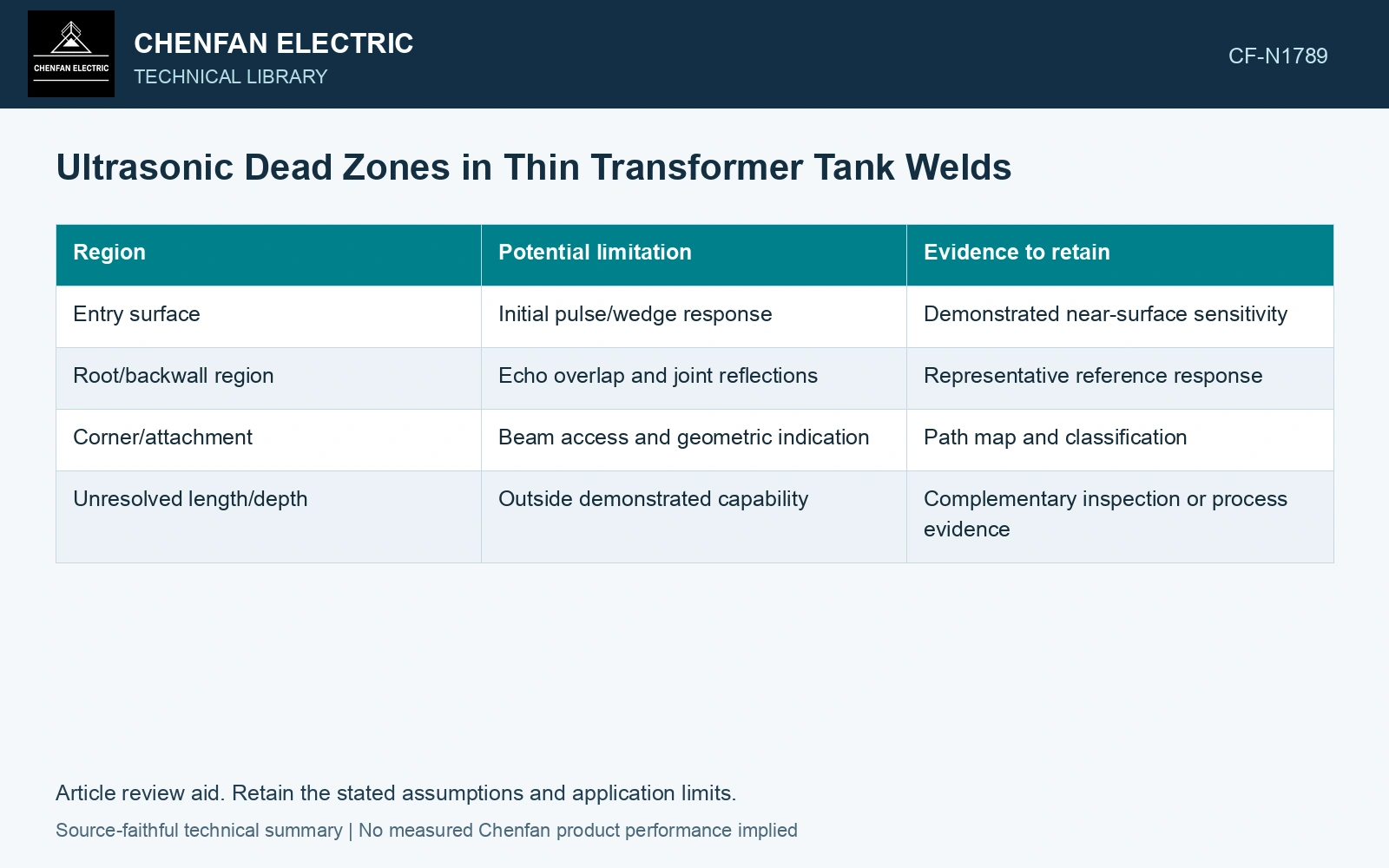
| Region | Potential limitation | Evidence to retain |
|---|---|---|
| Entry surface | Initial pulse/wedge response | Demonstrated near-surface sensitivity |
| Root/backwall region | Echo overlap and joint reflections | Representative reference response |
| Corner/attachment | Beam access and geometric indication | Path map and classification |
| Unresolved length/depth | Outside demonstrated capability | Complementary inspection or process evidence |
Choose NDT using material, weld thickness, welding process, quality requirements and demonstrated coverage. NDT acceptance levels are not a detailed one-to-one translation of weld quality levels. [2]
Calculate the available echo separation
Assume a 4 mm normal-beam steel path at 20 °C with acoustic speed 5,900 m/s. Round-trip time is 2×0.004/5,900 = 1.356 μs. If the demonstrated instrument/probe dead interval is an assumed 2 μs, this backwall return lies inside it. Select and demonstrate a method that addresses the unresolved region; catalogue frequency alone is insufficient.
Demonstrate before assigning coverage
Use representative thickness, material and joint references under the qualified examination plan. Show that the feature of concern can be distinguished from the geometry. A flat calibration block may not represent a corner seam’s root response.
References
- U.S. Federal Highway Administration, Bridge Welding Reference Manual, FHWA-HIF-19-088, 2019.
- ISO, ISO 17635:2025, Non-destructive testing of welds — General rules for metallic materials.