

Paint near a bolted radiator flange sees compression under hardware and possible shear during assembly. Damage after tightening may therefore follow a different mechanism from poor adhesion on an untouched panel. Inspect the assembled joint and the coating history together. [1]
Locate each damaged area relative to washers, bolt heads, gasket contact and flange edges. Record whether the coating was fully qualified for assembly at that time. Do not infer the tightening load from paint appearance alone.
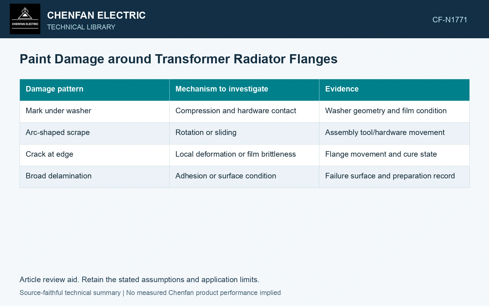
| Damage pattern | Mechanism to investigate | Evidence |
|---|---|---|
| Mark under washer | Compression and hardware contact | Washer geometry and film condition |
| Arc-shaped scrape | Rotation or sliding | Assembly tool/hardware movement |
| Crack at edge | Local deformation or film brittleness | Flange movement and cure state |
| Broad delamination | Adhesion or surface condition | Failure surface and preparation record |
Keep sealing and coating questions separate
The gasket sealing path and protective paint boundary may overlap but have different requirements. Use the joint drawing to determine where paint is intended, where contact is required and how exposed edges are protected. A paint repair cannot be treated as a solution for flange distortion or a leaking gasket.
Likewise, removing all coating beneath hardware is not a generic remedy. It changes corrosion protection and possibly the joint interface. Any change needs the approved mechanical and coating detail.
The bolted joint’s actual preload and bearing area determine nominal contact pressure; torque or paint marks alone do not measure either. Preserve the approved washer/flange and coating detail when investigating assembly damage. [2]
Screen the hardware contact before selecting a paint repair
Assumptions at 20 °C: bolt preload is 20 kN and a sufficiently stiff washer has 40 mm outer and 22 mm inner contact diameters, with uniform annular pressure for this screen. Area is π(40² − 22²)/4 = 876.50 mm² and nominal bearing pressure 20,000/876.50 = 22.82 MPa. Against an assumed coating-interface assembly qualification of 15 MPa, it fails by 7.82 MPa. Holding the same preload and hole, the nominal area condition alone requires outer diameter at least √[22² + 4×20,000/(π×15)] = 46.71 mm. Hold the interface design for an approved coating/hardware resolution; do not reduce gasket clamping load or change washer geometry solely to repair the paint. Check nonuniform contact and the flange’s sealing/bonding requirements separately. [2]
References
- ISO, ISO 12944-7:2017, Paints and varnishes — Corrosion protection of steel structures by protective paint systems — Part 7: Execution and supervision of paint work.
- R. T. Barrett, Fastener Design Manual, NASA Reference Publication 1228, 1990.