

A cooler bypass changes the enthalpy split between cooled and bypass oil [1]. The inlet temperature represents the mixture only when its sensor is downstream of an adequately mixed junction. Record branch mass flows and sensor position before interpreting the controller response.
Begin with the mixing boundary
For steady mixing of the same oil with negligible heat loss and approximately equal heat capacity, Tmix = (ṁcTc + ṁbTb)/(ṁc + ṁb). Subscripts c and b denote cooler and bypass streams; mass flows are kg/s and temperatures use a common scale. Use enthalpies rather than the simple temperature average if properties differ materially.
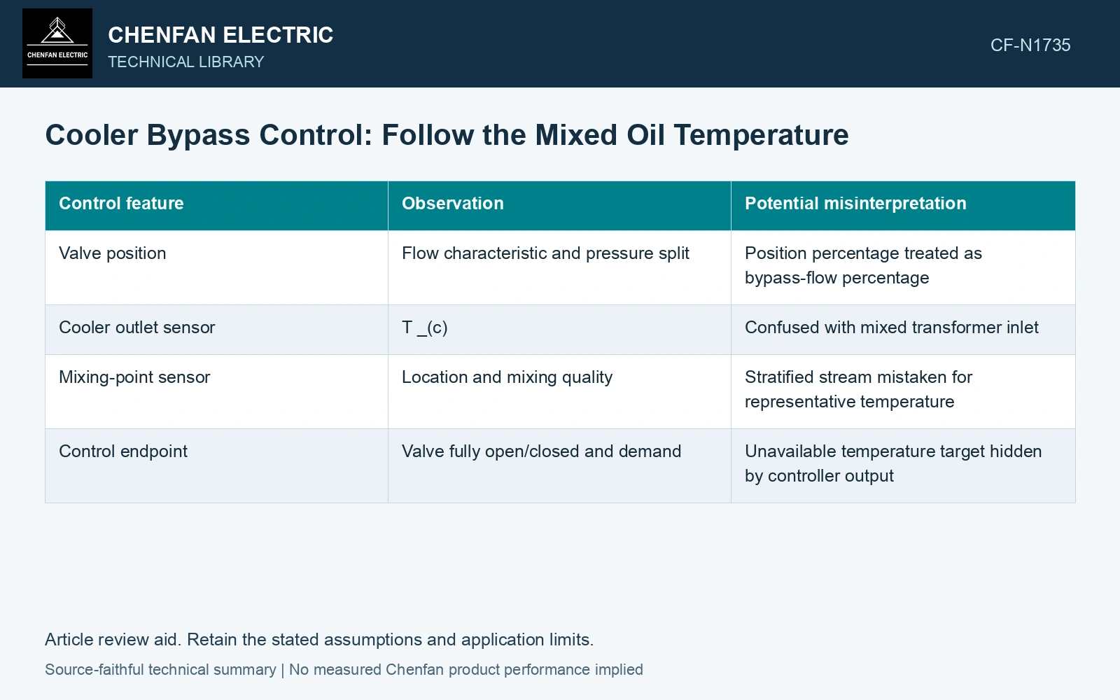
| Control feature | Observation | Potential misinterpretation |
|---|---|---|
| Valve position | Flow characteristic and pressure split | Position percentage treated as bypass-flow percentage |
| Cooler outlet sensor | Tc | Confused with mixed transformer inlet |
| Mixing-point sensor | Location and mixing quality | Stratified stream mistaken for representative temperature |
| Control endpoint | Valve fully open/closed and demand | Unavailable temperature target hidden by controller output |
Check light-load and cold-water endpoints
At low heat load or cold water, the controller may reach an endpoint while the inlet temperature continues beyond its intended band. At the other extreme, full cooler flow may still be insufficient for the target. Record these saturation states separately from ordinary regulation.
Preserve the minimum oil flow required through the transformer and through the cooler. A bypass changes both thermal and hydraulic behavior; reducing one stream does not necessarily reduce total pump flow proportionally.
Maintenance guidance documents cooling paths obstructed behind an apparently open valve [2]. Check the physical flow path when valve indication and mixed temperature disagree.
Reproduce the mixed inlet temperature
Assume equal heat capacities, 2 kg/s cooled oil at 40 °C and 1 kg/s bypass oil at 70 °C. Mixed temperature is (2×40 + 1×70)/3 = 50 °C. Reversing the mass split gives 60 °C. Verify branch flow and sensor mixing before attributing the warmer inlet solely to exchanger fouling.
For an assumed 55 °C mixed-oil target with the same 40 °C and 70 °C branch endpoints, the cooled mass fraction is (70 − 55)/(70 − 40) = 0.50. At 3 kg/s total, each branch needs 1.5 kg/s. Verify this flow split and minimum-flow constraints before mapping it to a valve command.
References
- U.S. Department of Energy, DOE-HDBK-1012/2-92, Thermodynamics, Heat Transfer, and Fluid Flow, Volume 2, 1992.
- U.S. Bureau of Reclamation, FIST Volume 3-30, Transformer Maintenance, 2000.