

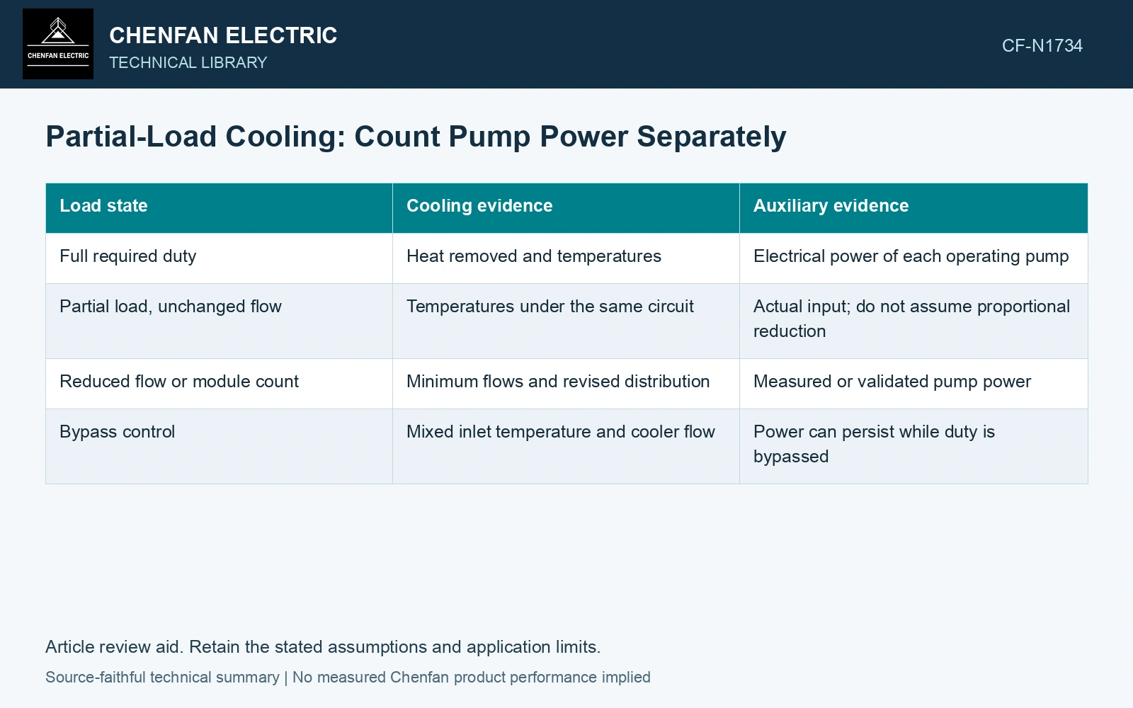
At partial transformer load, less heat may need to be removed while constant-speed oil and water pumps continue using power. Cooling performance and auxiliary consumption should be plotted separately. A lower oil temperature does not by itself demonstrate efficient operation. [1]
Define the system boundary: cooler modules, oil pumps, water pumps and any upstream chilled or circulating-water equipment included in the comparison. Retain transformer losses and cooling auxiliaries as separate quantities.
Use an operating map with two outputs
| Load state | Cooling evidence | Auxiliary evidence |
|---|---|---|
| Full required duty | Heat removed and temperatures | Electrical power of each operating pump |
| Partial load, unchanged flow | Temperatures under the same circuit | Actual input; do not assume proportional reduction |
| Reduced flow or module count | Minimum flows and revised distribution | Measured or validated pump power |
| Bypass control | Mixed inlet temperature and cooler flow | Power can persist while duty is bypassed |
Do not overextend pump affinity laws
For a geometrically similar pump under appropriate conditions, flow scales approximately with speed, head with speed squared and power with speed cubed. Real installed performance also depends on static head, efficiency and the system curve. Use these relations as a screen, then verify the actual operating point.
Maintain the cooler and transformer minimum-flow requirements from their design. Reduced heat load does not prove that oil circulation through winding ducts can be reduced arbitrarily. Module switching can also change branch flow and control stability.
Transformer maintenance guidance describes staged oil-pump/fan operation and checking the resulting oil circulation [2]. Any auxiliary-power change must retain the cooling stage required by the actual load and temperature duty.
Keep the pump saving on its own ledger
Assume a suitable similar-pump screen with unchanged efficiency and negligible static-head effect. Reducing speed to 0.8 pu gives approximate shaft power 0.8³ = 0.512 pu. For an assumed 10 kW starting power, the screen predicts 5.12 kW, saving 4.88 kW. Verify the actual system curve and transformer temperature duty before claiming that saving.
Assume this operating state lasts 1,000 h. The conditional saving is 4,880 kWh, while the transformer loss remains on a separate ledger. Meter the complete electrical auxiliary boundary, including drive and upstream water equipment, before reporting an energy saving.
References
- U.S. Department of Energy, DOE-HDBK-1012/3-92, Thermodynamics, Heat Transfer, and Fluid Flow, Volume 3, 1992.
- U.S. Bureau of Reclamation, FIST Volume 3-30, Transformer Maintenance, 2000.