

Commutation failure in an LCC bridge changes how current transfers between valves. The resulting transformer duty depends on the actual conducting combination and the event duration. A single missed transfer and repeated failures need separate current histories. Apply the HVDC transformer specification framework of IEC/IEEE 60076-57-129 to the stated liquid-immersed equipment [1].
Use the station transient model or recorded valve and phase currents. Label each conducting valve and the AC terminal it connects. Reconstruct phase currents with a consistent sign convention before referring them through the transformer vector connection.
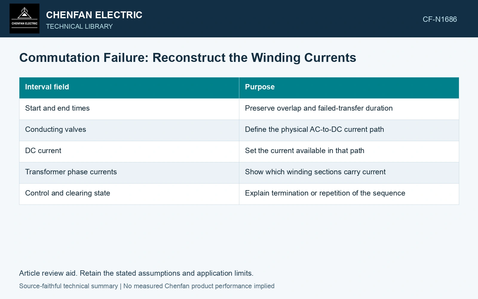
A conduction ledger that can be audited
| Interval field | Purpose |
|---|---|
| Start and end times | Preserve overlap and failed-transfer duration |
| Conducting valves | Define the physical AC-to-DC current path |
| DC current | Set the current available in that path |
| Transformer phase currents | Show which winding sections carry current |
| Control and clearing state | Explain termination or repetition of the sequence |
Do not infer that the intended firing pulse caused successful conduction. Voltage depression, overlap and valve recovery affect the actual transfer. The conducting-state record should agree with the calculated or measured phase currents.
Retain asymmetry as well as heating
For a simplified winding heating comparison, integrate ∫i²(t)dt for each phase over the complete event. The result has units A²s. Multiplication by a constant resistance in ohms yields joules, but real resistance and additional losses can vary with temperature and frequency.
Also retain current peaks and signed averages. Two histories can have a similar heating integral and different peak force or magnetic imbalance. Repeated failures can change the core’s initial state for the next interval, so concatenating identical isolated-event waveforms may be inadequate.
Compare equal heating with unequal current peaks
Assume rectangular phase-current screening histories of 2 kA for 0.10 s and 1 kA for 0.40 s, at the same initial temperature and constant winding resistance 0.010 Ω. Both give ∫i²dt = 400,000 A²s and resistive energy 4.0 kJ. Their peak-current ratio is 2, giving a force ratio of 4 only under unchanged linear geometry and current distribution. Thus equal heating does not clear the higher-peak case: retain both the current-squared integral and the synchronized force inputs.
State what the study actually covers
Specify the initiating AC disturbance, bridge group, control response, initial load and fault-clearing action. Check every winding using the multiwinding model; a line-current record on one terminal does not automatically reveal internal delta current.
Compare the time-indexed winding current with equipment data using separate heating, peak and asymmetry measures. Two sequences with equal heating integrals may impose different mechanical peaks. These measures do not yield a universal permissible count of commutation failures.
Include normal converter operation and converter-side faults in the transformer transient study [2].
References
- IEC/IEEE, IEC/IEEE 60076-57-129:2017, Power transformers – Part 57-129: Transformers for HVDC applications.
- CIGRE WG B4.51, Technical Brochure 609, Study of Converter Transients Imposed on the HVDC Converter Transformers, 2015.