

An LCC valve misfire can create an asymmetric conduction sequence. Whether it produces a DC ampere-turn imbalance in the converter transformer depends on which valve conducts, which current paths persist and how long the condition lasts. Assigning the same “DC bias” to every misfire loses this distinction. Apply the HVDC transformer specification framework of IEC/IEEE 60076-57-129 to the stated liquid-immersed equipment [1].
Label the bridge valves and transformer phase terminals. Starting from the defined pre-fault state, list the conducting valves for each interval. Include current continuity through the DC circuit and the relevant converter control response. The intended firing order is not evidence of the faulted conduction order.
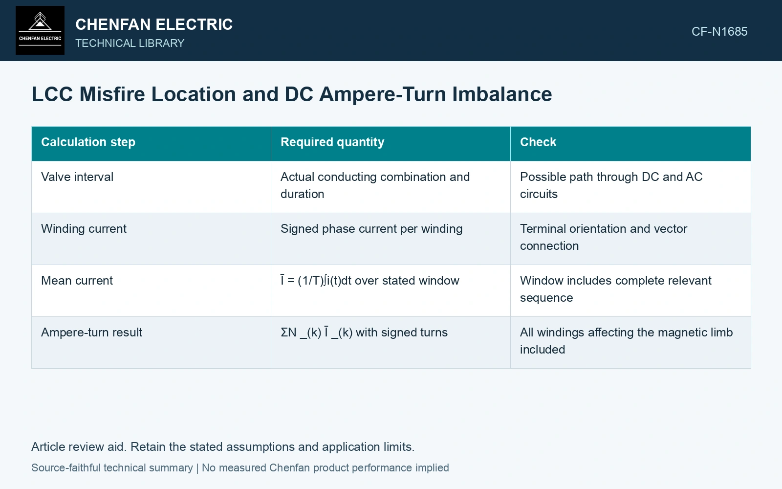
Convert the sequence into magnetic quantities
| Calculation step | Required quantity | Check |
|---|---|---|
| Valve interval | Actual conducting combination and duration | Possible path through DC and AC circuits |
| Winding current | Signed phase current per winding | Terminal orientation and vector connection |
| Mean current | Ī = (1/T)∫i(t)dt over stated window | Window includes complete relevant sequence |
| Ampere-turn result | ΣNkĪk with signed turns | All windings affecting the magnetic limb included |
Mean current is in amperes, N is the turn count and the signed sum is ampere-turns. A nonzero average in one winding alone does not establish net core magnetization; opposing contributions from other windings must be considered.
Keep mean ampere-turns and volt-seconds separate
Assume a 50 ms event window: a 1000-turn winding has mean current +2 A, while an opposing 100-turn winding has mean current −19 A. Their signed sum is 1000 × 2 − 100 × 19 = 100 A-turns, rather than the 2000 A-turns inferred from the first winding alone. Separately, an assumed mean induced voltage of 2 V on the 1000-turn winding changes linked flux by 2 × 0.050/1000 = 0.00010 Wb. Use the imbalance to select the coupled magnetic case; use corrected voltage history to calculate flux change.
Flux drift needs voltage history too
Faraday’s relation gives ΔΦ = (1/N)∫vinduced(t)dt, with induced winding voltage in volts, time in seconds and flux in webers. Terminal voltage differs from induced voltage by resistive and leakage terms. A current average cannot substitute directly for this flux integral in a saturated, dynamically coupled circuit.
Use the ampere-turn sum as a diagnostic for magnetic imbalance and the coupled circuit model to evaluate the core response. Retain initial flux, detection time and clearing action. A long-lived asymmetric sequence can have a different result from a rapidly cleared event at the same fault location.
Resolve each LCC valve fault into its winding-current windows and imbalance before applying the transformer duty. Missing valve-control or magnetic information limits that result. An MMC submodule fault follows a different conduction topology and cannot inherit the LCC table.
Include normal converter operation and converter-side faults in the transformer transient study [2].
References
- IEC/IEEE, IEC/IEEE 60076-57-129:2017, Power transformers – Part 57-129: Transformers for HVDC applications.
- CIGRE WG B4.51, Technical Brochure 609, Study of Converter Transients Imposed on the HVDC Converter Transformers, 2015.