

After a turbine trip, some auxiliaries stop immediately, some coast and others must continue running. The unit auxiliary transformer can therefore see a falling active load alongside a brief transfer or reacceleration current. One pre-trip MVA value cannot represent the sequence. Set the general power-transformer specification under IEC 60076-1 [1].
Start with the plant trip logic and a tagged motor list. Identify lubrication, cooling and other retained duties using the actual operating requirements. Separate loads that remain connected from loads that disconnect and subsequently restart. Coasting motors can maintain residual bus voltage even while their supply path is open.
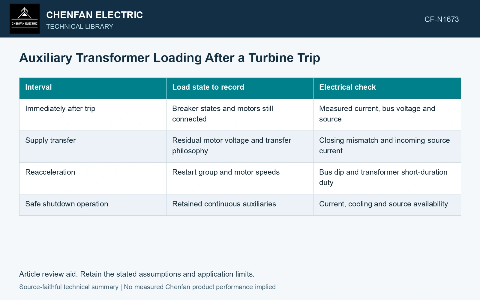
Write the load as a timeline
| Interval | Load state to record | Electrical check |
|---|---|---|
| Immediately after trip | Breaker states and motors still connected | Measured current, bus voltage and source |
| Supply transfer | Residual motor voltage and transfer philosophy | Closing mismatch and incoming-source current |
| Reacceleration | Restart group and motor speeds | Bus dip and transformer short-duration duty |
| Safe shutdown operation | Retained continuous auxiliaries | Current, cooling and source availability |
The intervals have no universal duration. Use event records or the validated dynamic study. Loads can overlap, and automatic restart delays can move the worst current away from the initial trip instant.
Keep the incoming source in the calculation
A transfer from the unit supply to a startup supply changes source impedance and possibly bus phase angle. The same motor group can produce a different voltage dip on the new source. If temporary parallel operation is permitted, include circulating current between supplies; if open transfer is used, include motor residual voltage and speed at reconnection.
For thermal assessment, retain the transformer temperature immediately before the trip. The short current pulse adds heat to an already loaded winding. The later retained load determines whether temperature falls, plateaus or continues to rise. Cooling auxiliaries may themselves be affected by the transfer.
Integrate the transfer stage separately from retained load
Assume winding RMS current of 1000 A during 2 s of reacceleration, followed by 300 A for 58 s, with constant resistance 0.010 Ω at the stated event temperature. Resistive energy over 60 s is 0.010 × (1000² × 2 + 300² × 58) = 72.2 kJ. Treating all 60 s as 300 A gives 54.0 kJ, 25.2% below the actual screening total. Preserve the reacceleration interval in the thermal input and assess its peak and incoming-bus voltage separately.
Verify the load list against recorded currents
Compare predicted stage currents with synchronized feeder and transformer measurements. A mismatch may reveal a load that remains connected, a failed restart or a timer differing from the logic drawing. Preserve those differences rather than forcing the event into the original load estimate.
A turbine trip changes the source state before it eliminates every auxiliary load. Size and study the surviving stages with their actual durations and supply paths; a single post-trip MW value would conceal both the transfer requirement and the remaining electrical burden.
For mineral-oil equipment, relate the loading assessment to operating temperature and thermal ageing [2].
References
- IEC, IEC 60076-1:2011, Power transformers – Part 1: General.
- IEC, IEC 60076-7:2018, Power transformers – Part 7: Loading guide for mineral-oil-immersed power transformers.