

A static-frequency converter can start a synchronous machine before it reaches synchronizing speed. Which transformer sees its startup current depends on where the converter input and output connect. A label reading “SFC start” on the plant schedule is insufficient to assign the duty. Set the general power-transformer specification under IEC 60076-1 [1].
Draw the converter as two ports. Follow its input back to the AC supply, then follow its output to the machine. Mark every transformer on each path and the bypass or starting switches used. The input current spectrum and the machine-side variable-frequency current are different quantities.
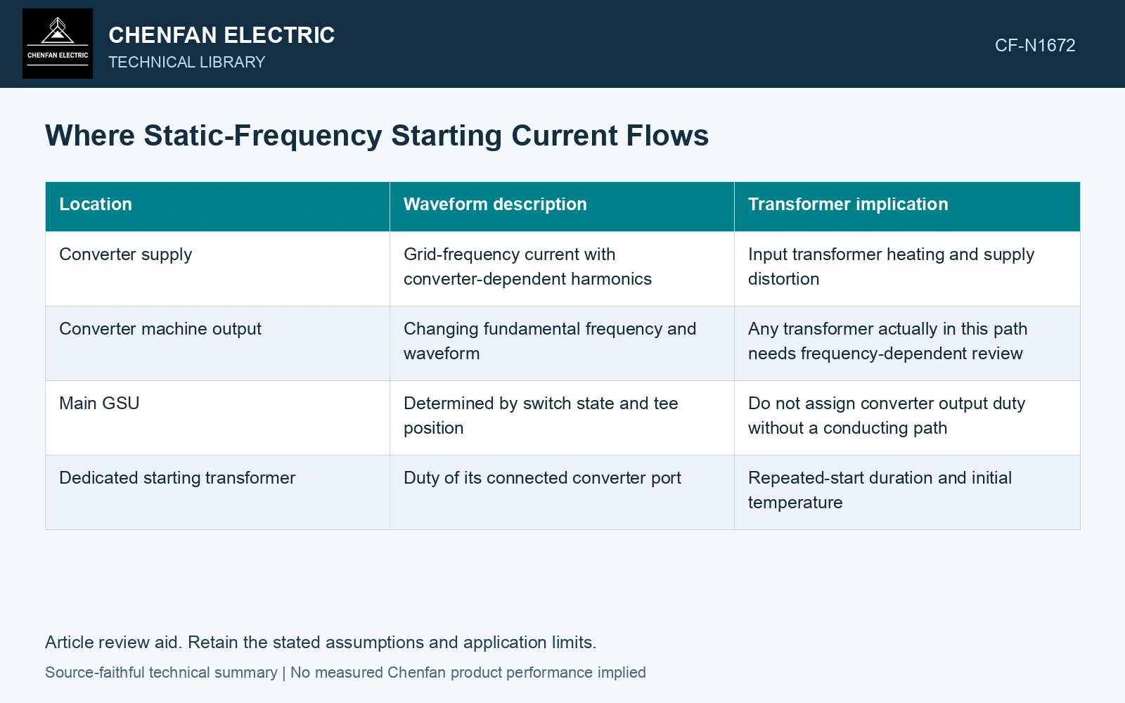
Place the waveform at the correct port
| Location | Waveform description | Transformer implication |
|---|---|---|
| Converter supply | Grid-frequency current with converter-dependent harmonics | Input transformer heating and supply distortion |
| Converter machine output | Changing fundamental frequency and waveform | Any transformer actually in this path needs frequency-dependent review |
| Main GSU | Determined by switch state and tee position | Do not assign converter output duty without a conducting path |
| Dedicated starting transformer | Duty of its connected converter port | Repeated-start duration and initial temperature |
A current spectrum is not just a THD number
Retain RMS magnitude by harmonic order, time through acceleration and the transformer terminal where it applies. For one winding current path in a first resistive estimate, Pdc = RΣIh², with R in ohms and each RMS harmonic current in amperes. Actual winding eddy and stray losses are frequency dependent, so equal total RMS current can produce different heating.
The simple sum assumes orthogonal periodic components over the averaging window and constant DC resistance. During frequency ramping, the window and frequency tracking matter. A stationary spectrum taken at one speed may miss another stage’s burden.
Assign harmonic copper loss to the input winding
Assume the SFC input transformer carries orthogonal RMS components of 100 A at 50 Hz, 20 A at 250 Hz and 10 A at 350 Hz, with resistance 0.10 Ω fixed at 75 °C. Total RMS is √(100² + 20² + 10²) = 102.47 A and resistive loss is 1.05 kW, 5% above the fundamental-only 1.00 kW. Assign this result to that input path. An open path to the main GSU gives it no share of these conductor currents; eddy losses still require their own frequency-dependent assessment.
Connect the start record to the repeated duty
Define unsuccessful starts, restart intervals and the maximum starting sequence required by the plant. Keep cooling status and initial temperature with each waveform. A transformer adequate for one cold start may require a different assessment for repeated hot starts.
Lastly, review the state change into normal generation. Identify which converter switches open, which main path closes and when the GSU becomes energized. This avoids placing one port’s harmonics on every transformer in the single-line diagram and gives each transformer a defensible startup duty.
For mineral-oil equipment, relate the loading assessment to operating temperature and thermal ageing [2].
References
- IEC, IEC 60076-1:2011, Power transformers – Part 1: General.
- IEC, IEC 60076-7:2018, Power transformers – Part 7: Loading guide for mineral-oil-immersed power transformers.