

After load rejection, generator terminal voltage and speed can both rise. The GSU core duty depends on their relationship. A high voltage reading alone does not show the highest flux, and a frequency rise alone does not prove the transformer is protected from overexcitation. Set the general power-transformer specification under IEC 60076-1 [1].
For approximately sinusoidal excitation, magnetic flux is proportional to V/f at a fixed winding and tap. Define r(t) = [V(t)/Vref]/[f(t)/fref], using the same terminal, line-voltage convention and frequency basis throughout. The ratio is dimensionless. It screens the dynamic trajectory against the transformer’s applicable excitation limits; it does not replace waveform-based flux integration for strongly distorted transients.
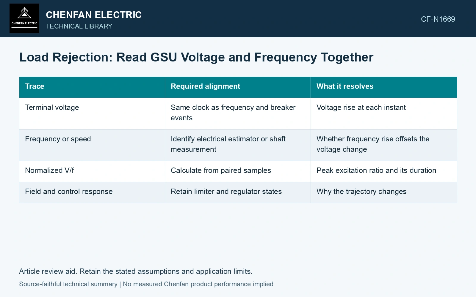
Timing decides which point matters
The turbine governor, excitation system and electrical disconnection respond through different mechanisms. A voltage rise may occur before a substantial speed increase. Later, frequency may be higher while voltage control has already reduced excitation. Plotting separate maximum values loses this timing.
| Trace | Required alignment | What it resolves |
|---|---|---|
| Terminal voltage | Same clock as frequency and breaker events | Voltage rise at each instant |
| Frequency or speed | Identify electrical estimator or shaft measurement | Whether frequency rise offsets the voltage change |
| Normalized V/f | Calculate from paired samples | Peak excitation ratio and its duration |
| Field and control response | Retain limiter and regulator states | Why the trajectory changes |
A ratio example without an operating recommendation
Assume two samples on one winding/tap base: an earlier 1.08 pu voltage at 1.00 pu frequency gives V/f = 1.080 pu; a later 1.10 pu at 1.05 pu frequency gives 1.04762 pu. The earlier ratio is 3.09% higher. Pairing the maximum voltage with the later maximum frequency would miss that earlier burden. Compare the full paired ratio and duration with the equipment excitation curve, keeping the actual tap as the voltage-per-turn reference.
Check the tap used to define the reference voltage. A ratio normalized to a convenient nominal bus voltage can conceal the actual voltage per turn. Confirm which winding voltage the excitation assessment uses and how measurement filtering affects short excursions.
Preserve the connection after rejection
Record whether the generator remains connected to the GSU and whether the grid-side breaker opens. The same turbine trip can leave different electrical sources in different plants. Add auxiliary supply changes and cooling availability to the event record.
Compare the paired V/f trace with the manufacturer’s time-dependent limit and the plant protection study. Do not invent a universal trip threshold from a textbook flux relation. The relation identifies the right evidence; equipment limits determine the permitted duty.
For mineral-oil equipment, relate the loading assessment to operating temperature and thermal ageing [2].
References
- IEC, IEC 60076-1:2011, Power transformers – Part 1: General.
- IEC, IEC 60076-7:2018, Power transformers – Part 7: Loading guide for mineral-oil-immersed power transformers.