

In a series-connected rectifier output, each bridge contributes part of the total DC voltage. Its AC supply winding can operate at a different absolute potential from another winding with the same local AC voltage. Insulation between groups and to ground must reflect that arrangement. IEC 61378-1 covers industrial converter-transformer specification, design and testing [1].
Define the DC grounding point and all bridge connections. A floating output stack and a stack grounded at one end have different absolute-potential relationships.
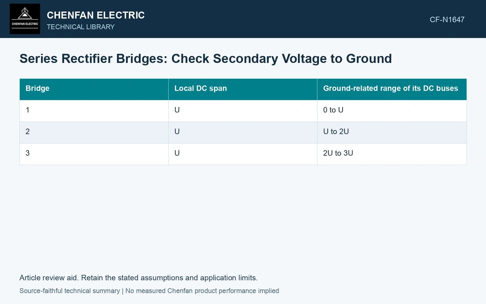
Establish the DC potential ladder
For an assumed three-bridge stack with equal DC increments U and the bottom negative bus at ground, the DC bus levels are 0, U, 2U and 3U. Bridge 1 spans 0 to U, bridge 2 spans U to 2U, and bridge 3 spans 2U to 3U.
| Bridge | Local DC span | Ground-related range of its DC buses |
|---|---|---|
| 1 | U | 0 to U |
| 2 | U | U to 2U |
| 3 | U | 2U to 3U |
This table defines bus potentials only. It does not assign the AC winding’s mean potential automatically to the midpoint. Conducting devices connect AC terminals to DC buses during particular states, while nonconducting intervals and parasitic capacitances determine other relationships.
Follow each secondary’s conducting connection
Map AC terminal potentials through the bridge states. Include the winding-to-core, winding-to-winding and lead-to-ground interfaces. A local turns voltage and a common-mode potential are different contributions to those duties.
Use the actual transient model for fast events. Capacitance to grounded structures and other windings can redistribute potential differently from the steady DC ladder. A simple arithmetic stack cannot establish impulse or switching stress.
Follow a conducting terminal up the DC stack
Assume three ideal series bridges each producing a 1 kV DC increment, with the bottom negative bus earthed. DC bus levels are 0, 1, 2 and 3 kV. During a defined state in which an AC terminal is clamped through an ideal conducting device to the upper bridge positive bus, that terminal is at 3 kV to earth. A corresponding lower-bridge positive-bus clamp is at 1 kV. The factor of 3 concerns these specific earth-related states, not AC turns voltage. Use the complete state map before selecting winding-to-earth insulation.
Recalculate after a fault or bypass
An unavailable, shorted or bypassed bridge can change the stack’s potential distribution. Define which devices and external grounding paths remain connected in each approved study case. Do not assume the original equal increments remain valid.
Check lead routes between bridges and their supports. An AC lead with a modest phase-to-phase voltage may still occupy the high-potential part of the DC stack. Its clearance to nearby grounded metal follows that actual potential relationship.
Compare design evidence and qualified tests with the relevant common-mode duty. A terminal ratio test does not validate insulation to the complete DC bus potential.
Record winding voltage, bridge position, grounding state and event condition separately for each secondary. Compare insulation and lead interfaces against the highest resulting local or intergroup potential in the required cases.
Retain an explicit measurement model and input uncertainties when comparing measured and calculated duty [2].
References
- IEC, IEC 61378-1:2011, Converter transformers – Part 1: Transformers for industrial applications.
- JCGM, JCGM 100:2008, Evaluation of measurement data — Guide to the expression of uncertainty in measurement, 2008.