

Two bridge groups can retain their designed phase relationship while carrying different DC currents. Their primary-referred harmonic contributions then differ in magnitude, leaving a residual that the ideal balanced comparison omits. IEC 61378-1 covers industrial converter-transformer specification, design and testing [1].
Keep the secondary voltage and phase relationship defined. Record each bridge’s DC current and AC conduction waveform. Use the actual winding transformation to refer those currents to the common primary.
Separate imbalance from angle error
For a harmonic pair intended to oppose, suppose the referred contributions are A and −B with the correct phase relationship. Their residual is A − B. An unequal bridge load can therefore produce a residual even with no transformer phase error.
If the relevant harmonic amplitude is proportional to DC current under a stated conduction model, write A = kI1 and B = kI2. Residual magnitude is then |k(I1 − I2)|. This scaling must be checked when overlap, discontinuity or firing strategy changes the waveform shape.
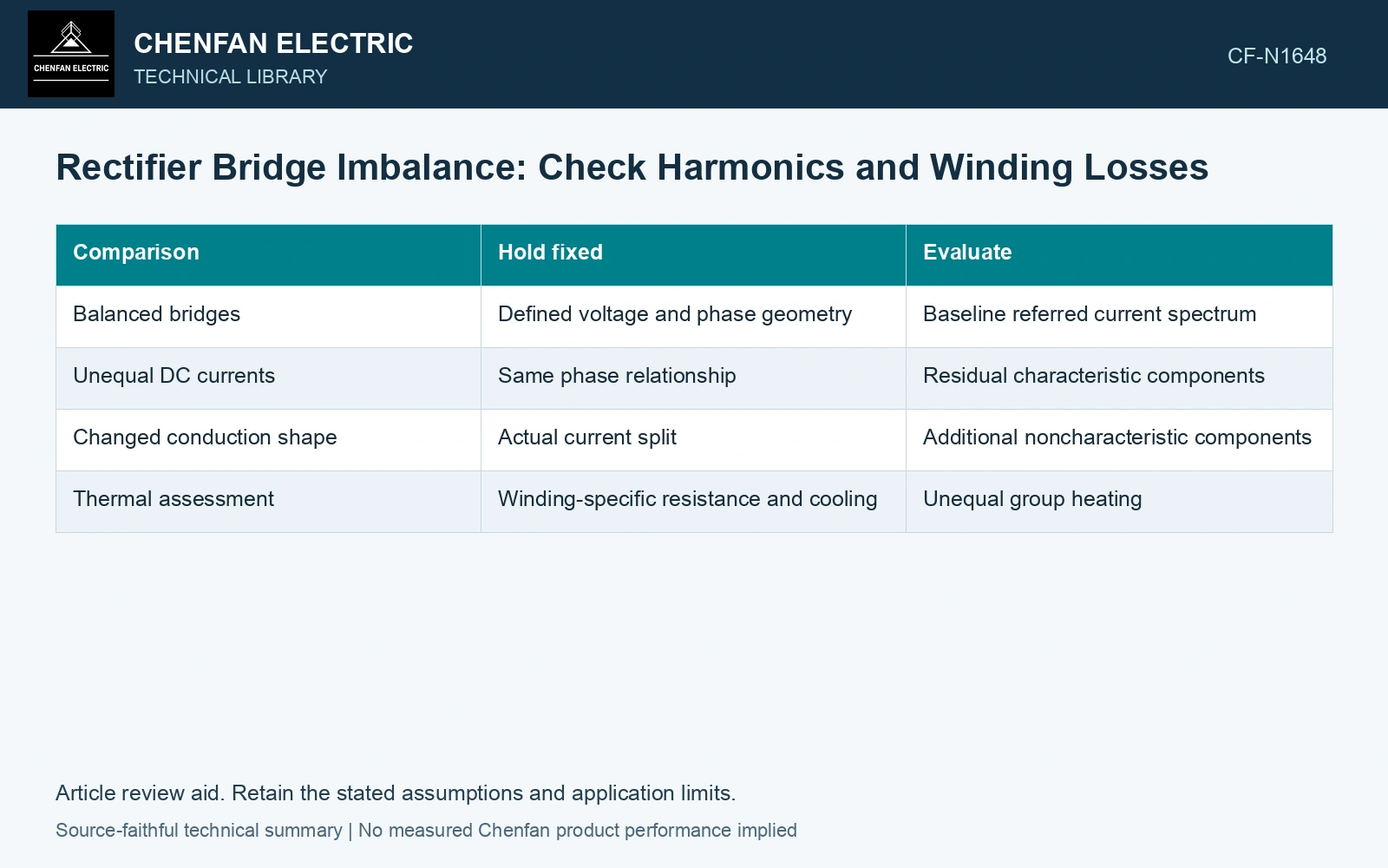
| Comparison | Hold fixed | Evaluate |
|---|---|---|
| Balanced bridges | Defined voltage and phase geometry | Baseline referred current spectrum |
| Unequal DC currents | Same phase relationship | Residual characteristic components |
| Changed conduction shape | Actual current split | Additional noncharacteristic components |
| Thermal assessment | Winding-specific resistance and cooling | Unequal group heating |
A constant total does not preserve copper loss
For an assumed equal-resistance pair with resistance R, loss is R(I1² + I2²) for the relevant RMS winding currents. Changing from 100/100 A to 120/80 A preserves the sum but raises the squared-current sum from 20,000 to 20,800 A², a 4% increase.
This example concerns equal-resistance winding currents, not a direct substitution of DC bridge current into every conductor. Derive the actual RMS mapping first. Additional frequency-dependent losses can change differently.
Calculate the residual before blaming the angle
Assume a harmonic whose correct primary-referred contributions are 100 A and −100 A RMS in balanced operation. If unequal bridge loading changes the second to −80 A without changing phase, residual is 20 A instead of zero. For equal 100 A contributions, a 5° angular mismatch alone would give 2 × 100 sin 2.5° = 8.72 A. In this example amplitude imbalance produces 2.29 times that angle-only residual. Check bridge sharing before changing phase-shift turns; use the actual RMS mapping for the separate copper-loss comparison.
Inspect the common primary and each secondary
The common primary carries the sum of referred contributions. Its residual harmonics do not reveal the entire thermal distribution in the secondary groups. One group can become limiting while total DC output remains within its previous value.
Use synchronized records so that the phase relationship remains testable. Report tap, source waveform, bridge control and current split with each comparison. A changed source background can otherwise be mistaken for an imbalance-generated component.
Set acceptance and operating constraints from the complete converter-transformer duty. A nominal twelve-pulse description cannot guarantee a harmonic result at every bridge-current split.
Define the simultaneous bridge-loading region by the limiting primary harmonic or secondary thermal duty. Recheck unequal loading even when total DC output remains balanced, because cancellation and loss distribution depend on the individual contributions.
Check ratio and phase on the actual special connection and selected tap [2].
References
- IEC, IEC 61378-1:2011, Converter transformers – Part 1: Transformers for industrial applications.
- Gandhi Jeyaraj, S., Milne, R., and Mitchell, G., On-Site Testing of Special Transformers, Megger technical paper, Sections 2–6.