

During commutation, current transfers between phases over a finite interval. The winding current therefore need not follow an ideal rectangular pulse. Its RMS value must be calculated from the current in that specific winding branch, including the transfer intervals. IEC 61378-1 covers industrial converter-transformer specification, design and testing [1].
Identify the bridge topology, DC-current state and source impedance. Derive or measure each phase’s waveform over a repeating period. Do not assign the DC output current directly to every AC conductor.
Integrate squared current by interval
The definition is Irms² = (1/T)∫₀ᵀi²(t)dt, with current in amperes and period T in seconds. For a linear ramp from zero to I over duration τ, the contribution to the integral is I²τ/3. A constant plateau of duration L contributes I²L.
For an assumed waveform containing positive and negative trapezoidal pulses, each with a plateau L and two zero-to-peak or peak-to-zero ramps of duration τ, Irms² = I²(2L + 4τ/3)/T. This describes the stated pulse geometry only; actual commutation may change pulse duration and shape differently.
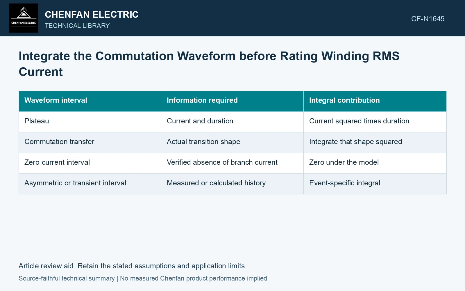
| Waveform interval | Information required | Integral contribution |
|---|---|---|
| Plateau | Current and duration | Current squared times duration |
| Commutation transfer | Actual transition shape | Integrate that shape squared |
| Zero-current interval | Verified absence of branch current | Zero under the model |
| Asymmetric or transient interval | Measured or calculated history | Event-specific integral |
Preserve the complete period
Changing ramp duration while leaving every other interval fixed can produce an impossible total period. Keep conducting and nonconducting intervals consistent with the actual switching sequence.
Commutation overlap can vary with load, voltage and source impedance. Evaluate the operating range rather than using one overlap angle for every current condition. For thyristor operation, firing strategy adds another waveform dependency.
Check whether the chosen quantity is phase winding current, line current or a partial winding-segment current. In a delta or polygon connection, these can differ. Integrating the wrong branch accurately still gives the wrong conductor duty.
Integrate a period whose intervals actually fit
Assume a 20 ms period and two opposite 100 A trapezoidal pulses, each with 6 ms plateau and two 1 ms ramps. Pulse intervals occupy 16 ms in total, leaving 4 ms at zero. RMS is 100√[(2 × 6 + 4 × 1/3)/20] = 81.65 A. Replacing each entire 8 ms pulse envelope by a 100 A rectangle gives 89.44 A and overstates mean-square current by 20%. Integrate the actual commutation shape for conductor heating while retaining peak and spectral duty separately.
Use RMS for its proper task
RMS supports resistive heating calculations, while frequency-dependent eddy and stray losses require spectral or waveform-dependent treatment. Peak current and electromagnetic force need their own assessment. One RMS number cannot establish all three.
Compare the ideal rectangular approximation with the actual integrated waveform and state its error over the relevant range. If it is adequate for a preliminary estimate, retain that bounded use. If it is not, the piecewise calculation provides the conductor duty directly without an unexplained correction factor borrowed from another rectifier arrangement.
Retain an explicit measurement model and input uncertainties when comparing measured and calculated duty [2].
References
- IEC, IEC 61378-1:2011, Converter transformers – Part 1: Transformers for industrial applications.
- JCGM, JCGM 100:2008, Evaluation of measurement data — Guide to the expression of uncertainty in measurement, 2008.