

A multi-pulse supply relies on the relationship between bridge contributions as seen at the common primary. Unequal secondary angles can disturb that relationship, but voltage magnitude and bridge loading can do so too. Test them separately before assigning the residual to a phase-shift error. IEC 61378-1 covers industrial converter-transformer specification, design and testing [1].
Refer the bridge current harmonics to one primary-side phase and time convention. The harmonic phase transformation depends on the actual winding connection and sequence. It should not be replaced automatically with harmonic order multiplied by the fundamental voltage shift.
Use a residual-vector comparison
Suppose two primary-referred harmonic contributions intended to oppose are A and −B exp(jε). Their residual is R = A − B exp(jε), giving |R|² = A² + B² − 2AB cos ε. Amplitudes are in amperes and ε is their residual angular mismatch.
For equal A = B, residual magnitude is 2A|sin(ε/2)|. With zero phase mismatch, it is |A − B|. This clearly separates phase and magnitude effects for the defined harmonic pair.
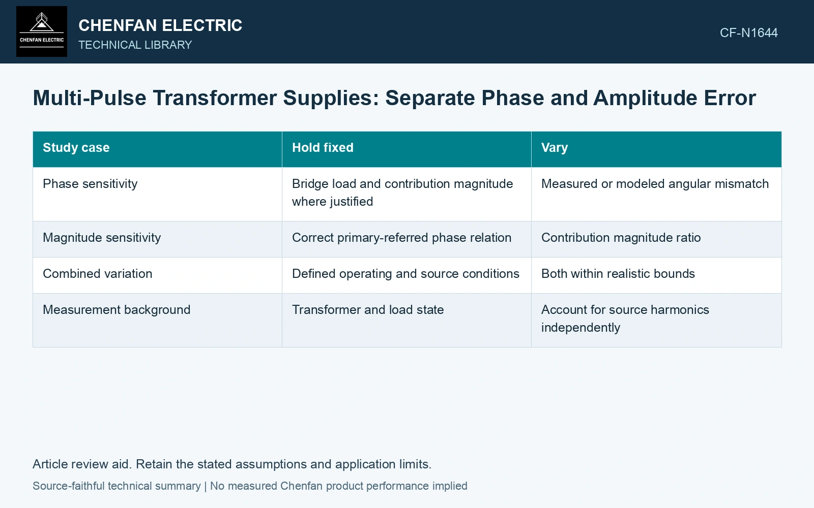
| Study case | Hold fixed | Vary |
|---|---|---|
| Phase sensitivity | Bridge load and contribution magnitude where justified | Measured or modeled angular mismatch |
| Magnitude sensitivity | Correct primary-referred phase relation | Contribution magnitude ratio |
| Combined variation | Defined operating and source conditions | Both within realistic bounds |
| Measurement background | Transformer and load state | Account for source harmonics independently |
The formula is a phasor illustration. Actual amplitudes may change when secondary voltage phase or magnitude changes, so a converter simulation or controlled measurement must capture that interaction.
Keep characteristic and other components distinct
Analyze each harmonic of interest and the phase-current symmetry. Unequal operation can introduce components outside an ideal balanced pattern. A total distortion metric compresses them and can hide which relationship changed.
Use synchronized channels and enough steady records to estimate repeatability. A timing mismatch can look like a transformer phase error. Record tap and bridge load because both may change the expected relationship.
Separate phase-only, amplitude-only and combined residuals
Assume primary-referred harmonic amplitudes 100 A and 90 A RMS intended to oppose, with residual angular error 3°. Their combined residual is √(100² + 90² − 2 × 100 × 90 cos 3°) = 11.17 A. Magnitude error alone gives 10.00 A; phase error alone with equal 100 A amplitudes gives 5.24 A. Compare those controlled cases before assigning the measured residual to phase-shift error. Synchronization and the actual harmonic sequence transformation remain part of the diagnosis.
Interpret the limiting cause
If residuals follow amplitude imbalance with nearly correct phase, investigate voltage magnitude and load sharing. If phases depart while loads remain controlled, investigate the connection, tap relationship and measurement convention. If both change, keep both in the model.
Compare residual components order by order, separating phase error from unequal contribution magnitudes. Apply the project’s acceptance criteria to that map, then correct the electrical relationship responsible for the limiting component.
Check ratio and phase on the actual special connection and selected tap [2].
References
- IEC, IEC 61378-1:2011, Converter transformers – Part 1: Transformers for industrial applications.
- Gandhi Jeyaraj, S., Milne, R., and Mitchell, G., On-Site Testing of Special Transformers, Megger technical paper, Sections 2–6.