

A polygon connection can combine several winding segments into each output. One reversed segment can alter magnitude, angle and loop balance. A conventional vector-group label may not describe the extra phase shift or reveal the error. IEC 61378-1 covers industrial converter-transformer specification, design and testing [1].
Treat the connection as a graph. Nodes are physical junctions and terminals; edges are winding segments with defined start, finish, turns and phase-linked induced voltage. Keep the physical identifier with every edge.
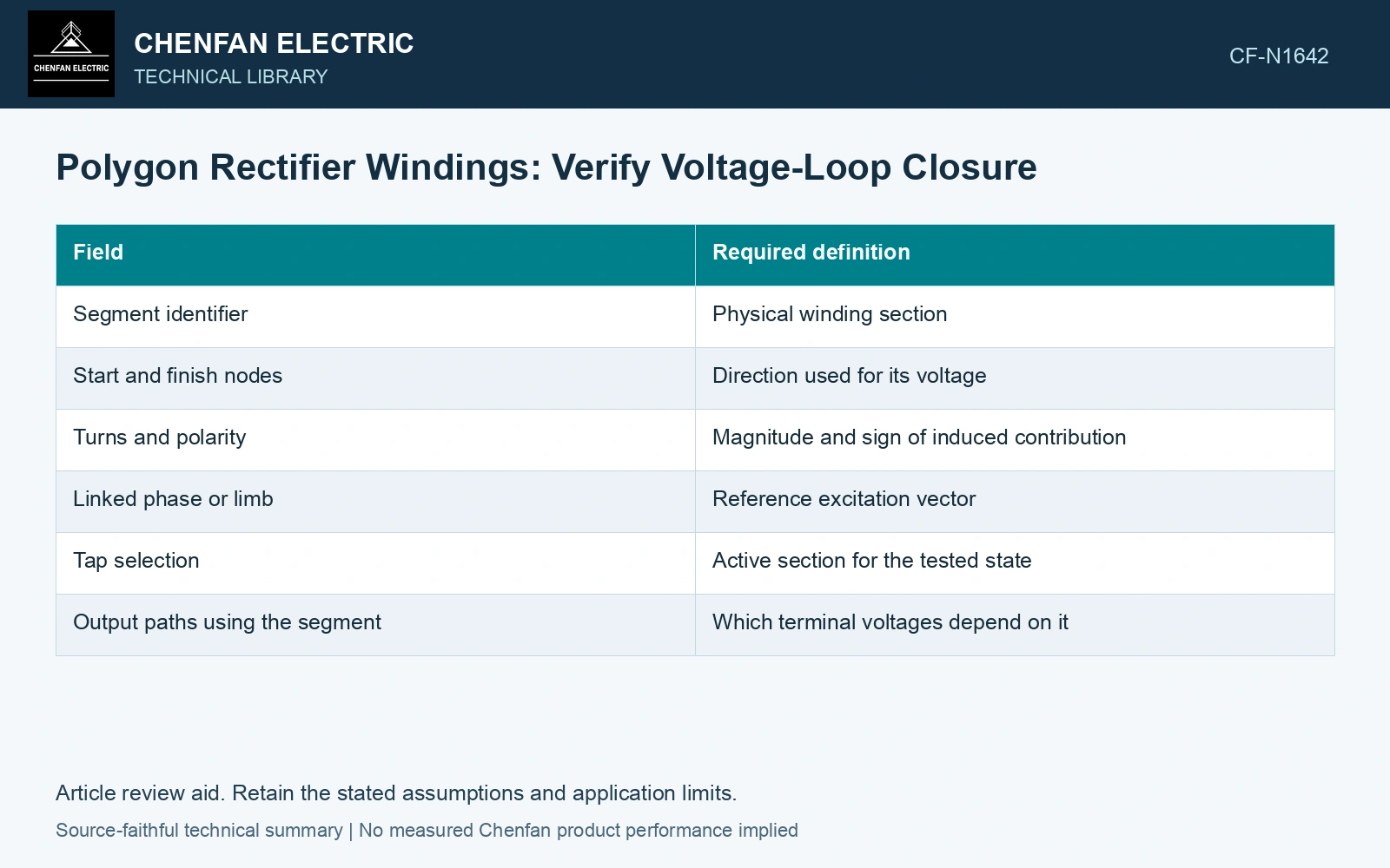
Build the signed segment table
| Field | Required definition |
|---|---|
| Segment identifier | Physical winding section |
| Start and finish nodes | Direction used for its voltage |
| Turns and polarity | Magnitude and sign of induced contribution |
| Linked phase or limb | Reference excitation vector |
| Tap selection | Active section for the tested state |
| Output paths using the segment | Which terminal voltages depend on it |
Calculate an output voltage by summing segment phasors along a defined path. Reverse a segment’s sign when the path traverses it against its reference direction. Do not substitute unsigned segment magnitudes.
Apply two independent checks
First calculate all required line-to-line output phasors. Compare their magnitude, phase sequence and displacement from the stated input reference. Use the same convention for every bridge group.
Second sum ideal induced-voltage phasors around each independent closed winding loop. A physically consistent ideal no-load loop should close under its assumed excitation. A nonzero sum can expose a connection, polarity or turn-definition discrepancy.
Do not conceal a failed closure by shifting the output reference angle. A common reference rotation changes every vector together; it cannot repair an incompatible loop sum.
Use a closed vector loop to expose one reversed section
Assume three ideal 50 Hz induced segment voltages of 100 V RMS at 0°, 120° and 240°, with reference arrows following one closed loop. Their signed sum is zero. Reversing the 240° segment changes the sum to 100∠0° + 100∠120° − 100∠240°, whose magnitude is 200 V RMS. A common rotation of the reference leaves that magnitude unchanged. Reject the candidate polarity assignment and verify the physical start/finish marks before treating any resulting circulation as a normal load effect.
Distinguish a wiring discrepancy from loaded behavior
The ideal path check excludes resistance and leakage drops. Under load, those drops and internal circulating currents require the actual circuit equations. A terminal-angle change under load does not automatically mean a segment is reversed.
Check each tap because selected segment proportions can change. A connection verified at nominal tap may have a different phase relationship elsewhere.
Use qualified ratio and phase tests whose expected readings are derived from the same graph. A test instrument may report a cumulative terminal ratio rather than the turns ratio of one segment. Its automatic group recognition is a convenience, not independent proof of the internal diagram.
If measured and calculated values disagree, compare terminal naming, phase sequence, selected tap and test configuration before changing the winding model. Keep candidates that remain unresolved within measurement capability.
The completed table and loop checks make the polygon connection reproducible. They turn a special phase-shift claim into a set of concrete terminal predictions that can be tested without pretending the connection is fully described by a standard clock number.
Check ratio and phase on the actual special connection and selected tap [2].
References
- IEC, IEC 61378-1:2011, Converter transformers – Part 1: Transformers for industrial applications.
- Gandhi Jeyaraj, S., Milne, R., and Mitchell, G., On-Site Testing of Special Transformers, Megger technical paper, Sections 2–6.