

Two regulating arrangements can produce the same terminal ratio while placing their active ampere-turns in different regions. One may use a neutral-side section on the main magnetic assembly; another may use an exciting and tap arrangement on a separate limb. The leakage field must be compared internally.
Compare the actual regulating-winding positions using the same terminal function, current references and operating state. A topology description alone does not quantify leakage-field improvement.
Match the electrical function first
For each candidate, derive connected turns, current paths and polarity at the compared tap. Use the same terminal voltages and simultaneous port powers where feasible. If one arrangement carries a different tertiary load or rating basis, its field result is not a like-for-like placement comparison. Record rated quantities and test conditions on the general power-transformer basis of IEC 60076-1 [1].
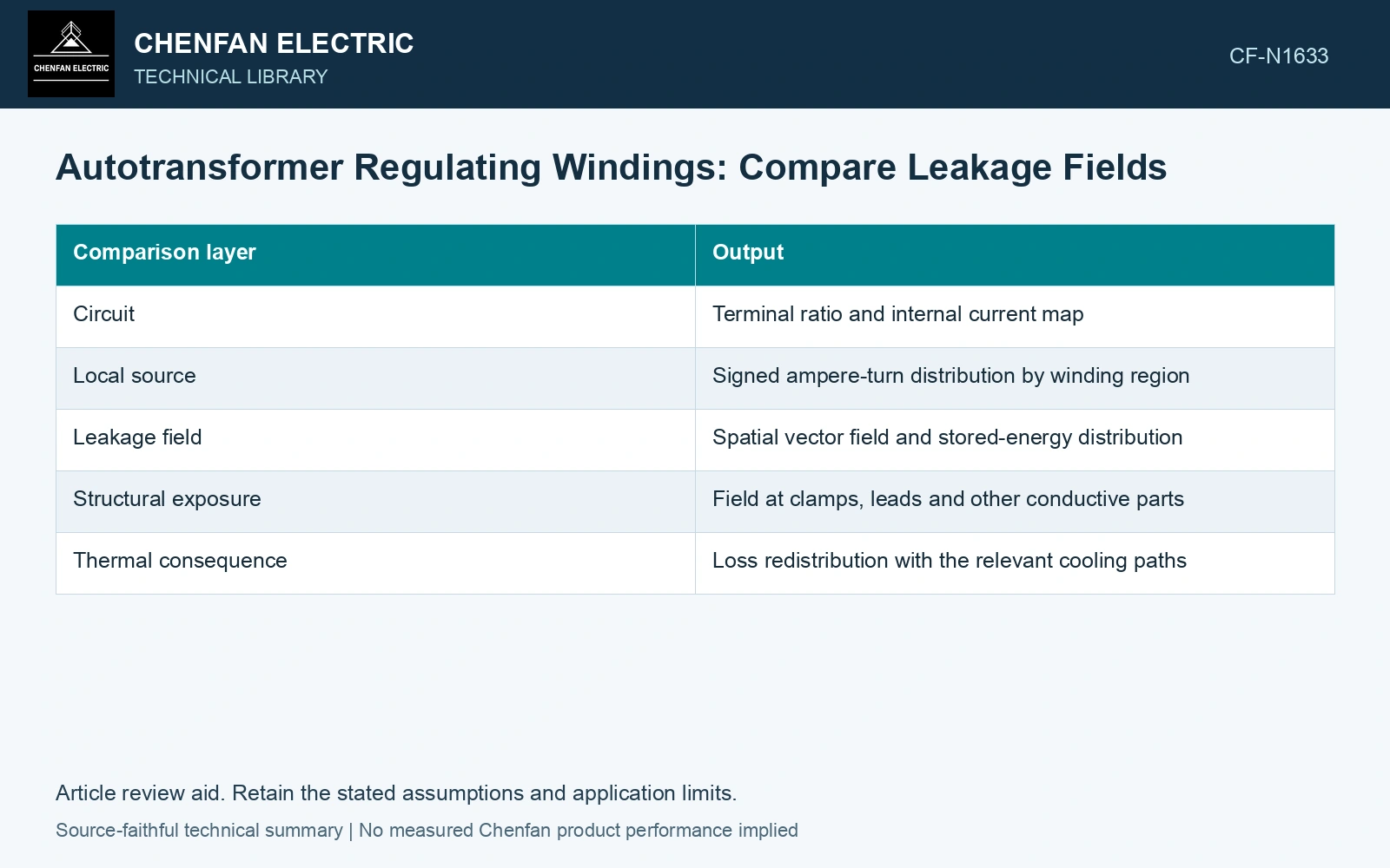
| Comparison layer | Output |
|---|---|
| Circuit | Terminal ratio and internal current map |
| Local source | Signed ampere-turn distribution by winding region |
| Leakage field | Spatial vector field and stored-energy distribution |
| Structural exposure | Field at clamps, leads and other conductive parts |
| Thermal consequence | Loss redistribution with the relevant cooling paths |
Inspect where the field changes
A total impedance value summarizes a port relationship. It does not identify which local gap or structural component carries the altered leakage field. Compare maps using the same field scale and region definitions.
Evaluate limiting tap positions as well as a nominal state. A placement that moderates one region at nominal tap can create a different demanding region when regulating current or selected turns change.
Keep the main magnetic excitation and auxiliary-limb excitation separate where the topology requires it. The assumption that both limbs share one fixed volts-per-turn state may not follow from their circuit.
Verify the relevant physical consequence
Check integrated leakage quantities and local field convergence. If structural heating is the concern, calculate or measure losses and temperatures using the actual conductive paths rather than equating field magnitude directly with temperature.
For force assessment, use the corresponding currents and field histories. A reduced global leakage energy does not establish that every winding or support force decreases.
The decision should name the region improved, any duty transferred elsewhere and the taps over which the conclusion holds. Terminal equivalence is the starting condition for the comparison; it does not prove internal equivalence. This distinction lets a reviewer assess a regulating proposal without relying on a topology label or a patent’s claimed percentage as a substitute for the actual design evidence. Assess the relevant measured quantities with a defined measurement model and propagated uncertainty [2].
Compare a local field reduction with displaced exposure
Assume the same 50 Hz port duty and geometry envelope for two regulating arrangements. In a linear leakage model, local RMS flux density at one clamp falls from 0.10 T to 0.08 T; a second location rises from 0.06 T to 0.09 T. If each location’s loss is screened with its own unchanged coefficient times B², the respective loss ratios are 0.64 and 2.25. The first location improves by 36%, while the second increases by 125%. Advance the arrangement only after the second region’s actual eddy-current and thermal duties are checked. A favorable field contour at the original hotspot is insufficient. Keep connection, tapping and network assumptions explicit in the application assessment [3].
References
- IEC, IEC 60076-1:2011, Power transformers – Part 1: General.
- JCGM, JCGM 100:2008, Evaluation of measurement data — Guide to the expression of uncertainty in measurement, 2008.
- IEC, IEC 60076-8:1997, Power transformers – Part 8: Application guide, 1997, official public scope.