

A winding’s turn count describes its intended repeated conductor loops. Its leads also form part of the complete circuit path. Depending on how they leave the core and return through the connected circuit, they may link additional magnetic flux.
The phrase “half-turn effect” is sometimes used as shorthand for a partial linkage associated with lead topology. It should not be interpreted as an automatic addition of exactly 0.5 to every winding turn count.
Close the path in the drawing
Trace the conductor from one terminal through the winding and back through the actual return circuit used by the assessment. Identify the magnetic regions enclosed by that path. Comparing two open lead sketches without their return paths cannot establish a loop flux.
Faraday’s law gives e = −dΨ/dt for the complete linked flux Ψ in webers. For a repeated winding around one well-defined flux, Ψ can be represented as NΦ. A lead linking a nonuniform or divided field may not admit one universal fractional N.
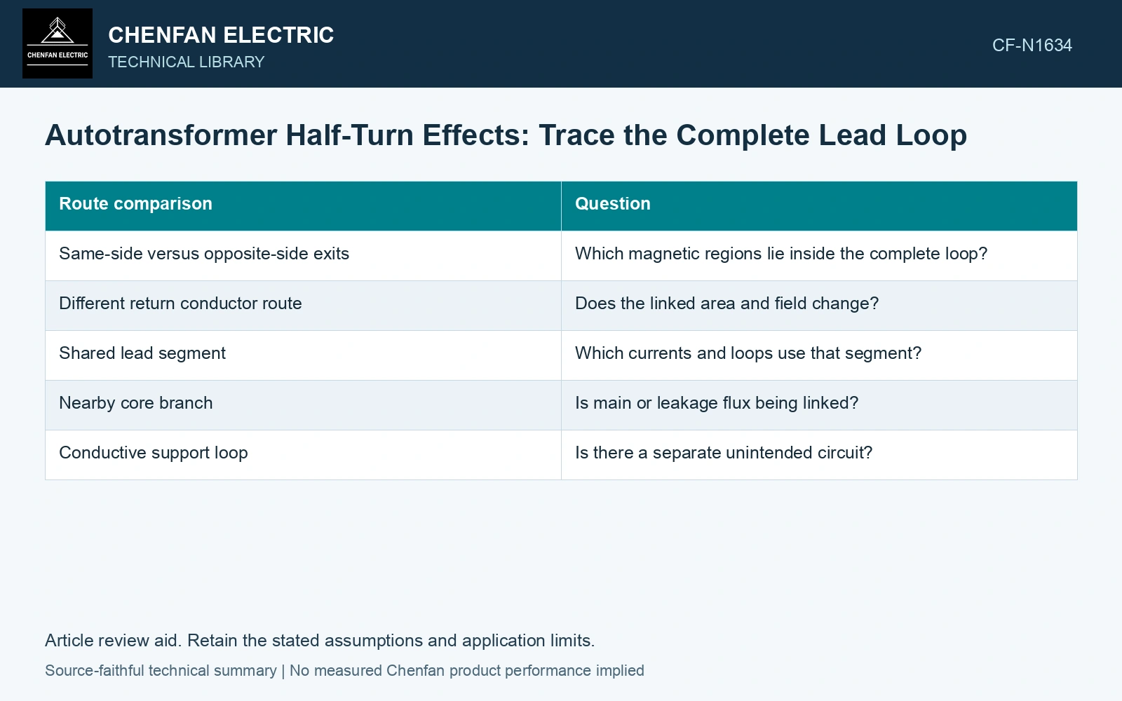
| Route comparison | Question |
|---|---|
| Same-side versus opposite-side exits | Which magnetic regions lie inside the complete loop? |
| Different return conductor route | Does the linked area and field change? |
| Shared lead segment | Which currents and loops use that segment? |
| Nearby core branch | Is main or leakage flux being linked? |
| Conductive support loop | Is there a separate unintended circuit? |
Distinguish voltage linkage from local MMF
A route can change induced voltage linkage and local current-field distribution. Those are related electromagnetic questions but not identical outputs. Compute the linked voltage for the stated loop and the local ampere-turn or field effect for the actual current path.
Keep polarity and terminal references explicit. A change in calculated voltage sign can come from a reversed loop convention rather than a physical design change.
For a three-dimensional field model, verify that conductor paths and current continuity match the circuit. An idealized winding block plus separately added lead current can duplicate or omit a segment if their boundaries are inconsistent. Assess the relevant measured quantities with a defined measurement model and propagated uncertainty [1].
Check the consequence at the relevant duty
Compare terminal behavior and local field exposure under the same operating condition. A small voltage effect may coexist with a local structural-metal heating concern, while a significant linkage difference may have little effect on one distant field location.
Use the calculation to identify a routing issue for approved design review. Do not alter a live or installed lead arrangement from a fractional-turn estimate alone; insulation, mechanical support and connection duties also belong to the route. Keep connection, tapping and network assumptions explicit in the application assessment [2].
Draw the closed lead path and identify the magnetic regions it links before assigning an induced voltage or duty. The resulting calculation should be reproducible from that path, without relying on an ambiguous half-turn description.
Calculate the voltage of the complete lead loop
Assume a complete lead-return loop links a sinusoidal flux of 0.20 mWb peak at 50 Hz. Faraday’s law gives eRMS = 2πfΨpeak/√2 = 0.0444 V. If the main-core flux is 10 mWb peak in this assumed state, the equivalent linkage fraction is 0.20/10 = 0.020 turn. Calling it a half turn would overstate this loop voltage by a factor of 25. Keep the calculated loop linkage with its route and polarity; obtain a new field integral if the return route changes. Record rated quantities and test conditions on the general power-transformer basis of IEC 60076-1 [3].
References
- JCGM, JCGM 100:2008, Evaluation of measurement data — Guide to the expression of uncertainty in measurement, 2008.
- IEC, IEC 60076-8:1997, Power transformers – Part 8: Application guide, 1997, official public scope.
- IEC, IEC 60076-1:2011, Power transformers – Part 1: General.