

The series winding sits between the high terminal and the common-winding tap. Its end-to-end voltage is their difference. Its voltage to grounded steel depends on their absolute potentials. A small end-to-end value therefore does not establish a low dielectric duty to ground.
State the voltage reference explicitly. For an illustrative single-phase grounded-neutral connection, suppose the high and low terminals are 100 and 80 kV RMS to neutral with aligned phasors. The series section has 20 kV across it, while its endpoints remain at 100 and 80 kV to neutral. These are circuit values, not insulation ratings.
Keep two potential descriptions
Let Vdiff = VH − VL and Vcm = (VH + VL)/2 for a defined pair of terminal phasors. The endpoints are Vcm ± Vdiff/2. This decomposition helps distinguish across-section stress from the section’s overall potential relative to the chosen reference.
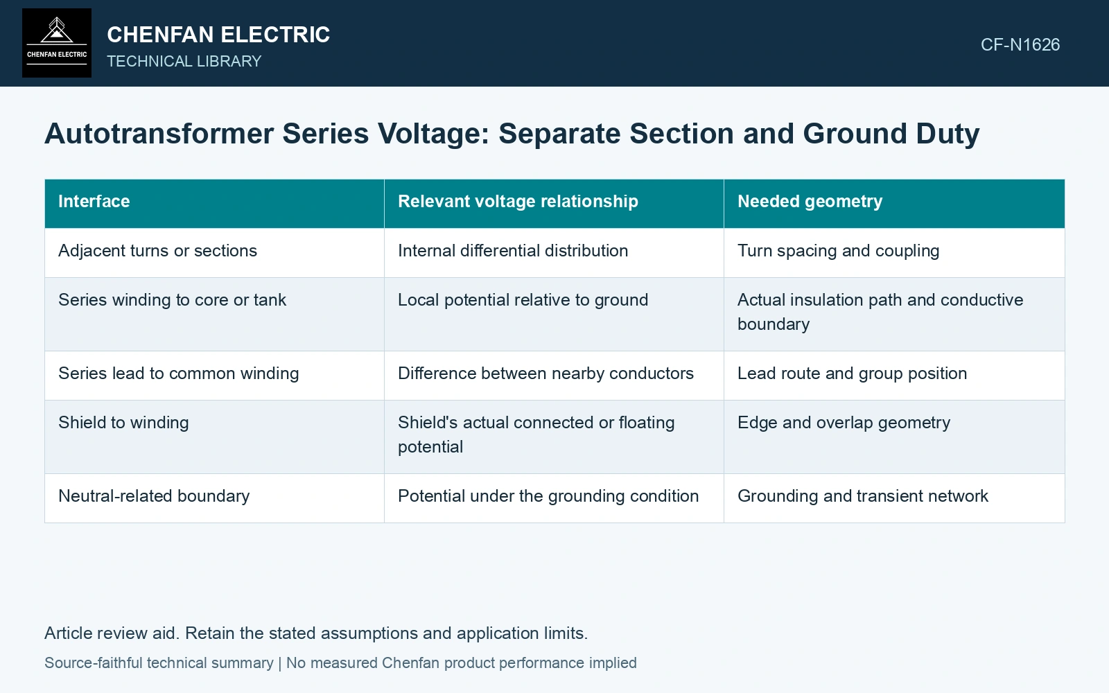
| Interface | Relevant voltage relationship | Needed geometry |
|---|---|---|
| Adjacent turns or sections | Internal differential distribution | Turn spacing and coupling |
| Series winding to core or tank | Local potential relative to ground | Actual insulation path and conductive boundary |
| Series lead to common winding | Difference between nearby conductors | Lead route and group position |
| Shield to winding | Shield’s actual connected or floating potential | Edge and overlap geometry |
| Neutral-related boundary | Potential under the grounding condition | Grounding and transient network |
Do not assign the entire section voltage uniformly to every turn. The steady induced-voltage distribution and transient distribution require their respective models. Capacitive coupling can produce a different initial impulse pattern from a turns-based division.
Ground is an operating assumption
The illustrative absolute potentials assume the stated neutral reference. Neutral displacement, grounding impedance or another connection changes the relationship to local ground. A potential to system neutral is not always identical to a potential to nearby grounded metal during a fault. All numerical inputs and limits in the illustrative cases are assumptions unless a catalogue or standard source is explicitly identified.
Use the actual voltage duties, including required transient cases. A shield can alter field distribution but also introduces its own edge and potential relationship. Label its connection rather than treating every metallic screen as ground by appearance. Keep connection, tapping and network assumptions explicit in the application assessment [1].
Inspect the high-potential route
Follow series leads and ends through their real geometry. A small-voltage regulating or series section can still require substantial clearance to ground along its route. The limiting region may be a lead transition rather than the winding body.
Compare the field assessment with the manufactured dimensions and accessible inspection features. Historical insulation-model data does not establish a criterion for a different interface without appropriate qualification.
The specification should state end-to-end, local conductor-to-conductor and ground-related duties separately. That prevents a buyer from interpreting “20 kV series voltage” as a complete dielectric description of a section physically located near a 100 kV terminal.
Reconstruct both endpoints from differential and common potential
Treat the 100/80 kV RMS example as an assumption at 50 Hz with neutral and local ground initially coincident. Then Vdiff = 20 kV and Vcm = 90 kV; 90 ± 10 kV reconstructs the two endpoints. An assumed +5 kV neutral displacement relative to local ground changes those endpoint potentials to 105 and 85 kV while leaving their difference at 20 kV. Specify the ground-related duty from the displaced endpoints and assess the local field separately. A section’s differential voltage cannot supply its ground-insulation rating [2]. Record rated quantities and test conditions on the general power-transformer basis of IEC 60076-1 [2]. Assess the relevant measured quantities with a defined measurement model and propagated uncertainty [3].
References
- IEC, IEC 60076-8:1997, Power transformers – Part 8: Application guide, 1997, official public scope.
- IEC, IEC 60076-1:2011, Power transformers – Part 1: General.
- JCGM, JCGM 100:2008, Evaluation of measurement data — Guide to the expression of uncertainty in measurement, 2008.