

Three core limbs can vibrate with similar amplitudes while contributing very differently to a microphone reading. At one position their pressure contributions may reinforce. Elsewhere the same sources may partly cancel because propagation and structural transmission introduce different phases.
Record limb responses against a shared electrical or measurement reference. Independent recordings with arbitrary start times cannot establish inter-limb phase, even if their amplitude spectra look identical.
Sum complex contributions at the receiver
In a linear harmonic illustration, let qⱼ be the complex source coordinate for limb j and Hⱼ(r,ω) its transfer function to receiver position r at angular frequency ω. The pressure is P(r,ω) = Σ Hⱼ(r,ω)qⱼ(ω). The source coordinate must be defined consistently, such as a specified modal displacement or strain input.
Both H and q carry phase. The squared magnitude of their sum contains cross terms. Adding the three individual squared magnitudes discards those terms and is appropriate only under a justified incoherence assumption.
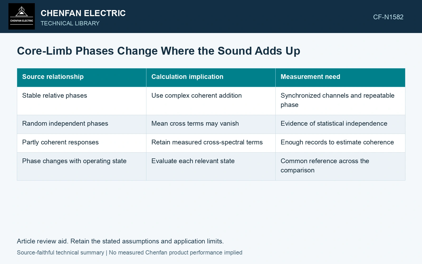
| Source relationship | Calculation implication | Measurement need |
|---|---|---|
| Stable relative phases | Use complex coherent addition | Synchronized channels and repeatable phase |
| Random independent phases | Mean cross terms may vanish | Evidence of statistical independence |
| Partly coherent responses | Retain measured cross-spectral terms | Enough records to estimate coherence |
| Phase changes with operating state | Evaluate each relevant state | Common reference across the comparison |
For two equal pressure contributions A, perfect phase agreement gives magnitude 2A. Opposite phase gives zero in the idealized model. Real sources rarely meet that cancellation condition over a broad region because their path differences vary with position and frequency.
Map the cancellation rather than declaring it universal
Evaluate several receiver positions around the assembly, including locations outside a suspected quiet region. Compare the relative phases and individual predicted contributions at each position. A low total can be sensitive to a small phase or geometry change when it relies on nearly equal opposing terms.
Separate limb motion from tank motion. Core supports, insulating liquid and tank modes can mix the original limb sources before they radiate. Assigning electrical phase displacement directly to the tank surface without checking that transmission skips the structural problem.
Use synchronized operating measurements to test the model. Check whether the measured response cross-spectra remain stable across repeated records. Low coherence can indicate changing operation, additional sources, noise in the measurement or an inadequate source description; it is not automatically proof that the limbs are independent.
A phase-aware result explains the directional field and its sensitivity. It can identify why one microphone becomes quiet while another becomes louder. It cannot support a general reduction claim based solely on a favorable position or a three-limb amplitude average.
Carry a sheet-based motion scale into coherent receiver addition
Use 0.23 mm catalogue sheet thickness [1]. Assume a 100-sheet, 100 mm wide steel section, giving area 0.00230 m², and a 0.50 m active length with 1.0 μstrain peak at 100 Hz. With assumed E = 200 GPa and full axial restraint, the eigenstrain reaction scale is EAε = 460 N peak. Suppose the complete frequency-domain transfer gives each of two such limb sources 0.010 Pa RMS at one receiver. In phase, total pressure is 0.020 Pa; at 120° relative phase it is 0.010 Pa, 6.02 dB lower. Three equal contributions at 0°, 120° and 240° cancel ideally at that receiver. Map other positions and phase uncertainty before accepting a sound-power benefit [2]. Directional strain under DC-biased and harmonic excitation requires its own source characterization [3].
Limb sheet section, joint sequencing and packet alignment control the magnetic geometry; clamp and support placement control the transmission path and modal phase. Record those variables by limb. Electrical phase displacement alone does not specify the complex tank-surface or receiver contribution.
References
- Nippon Steel Corporation, Grain-Oriented Electrical Steel Sheets, catalogue D004je_03_202004, 2020, Specifications; Size and Form Tolerances.
- COMSOL AB, Acoustics Module User’s Guide: The Pressure Acoustics, Boundary Elements Interface, version 6.3.
- Zhao, X., Du, Y., Liu, Y., Du, Z., Yuan, D., and Liu, L., Magnetostrictive Properties of the Grain-Oriented Silicon Steel Sheet under DC-Biased and Multisinusoidal Magnetizations, Materials 12, 2156, 2019. DOI: 10.3390/ma12132156.