

For a whole-body magnetic resultant, choose a closed integration surface in air that encloses exactly the intended free body and does not cross another magnetic body, a material interface or an applied-current region. Then move that surface within the same air region and refine the field mesh. The result is defensible only when both tests stabilize the force vector and moment. A large stress peak at a sharp joint corner is not, by itself, a reliable net force.
Start by deciding which body and which force are being evaluated. A complete packet’s resultant, the attraction between two joint faces and a local distributed structural load are different tasks. Their integration regions should not be chosen interchangeably. In particular, an exterior surface around the complete assembly cannot separate internal joint-face forces.
Use the formulation that belongs to the region
In vacuum, the magnetic Maxwell tensor is T = (BB − ½B²I)/μ₀. Integrating its traction Tn over a closed surface gives the magnetic resultant on the enclosed body under this formulation [1][2]. Here BB is the dyadic product, B is magnetic flux density, n is the outward unit normal and μ₀ is the vacuum permeability.
Writing B = Bnn + Bt shows what the surface traction contains:
t = Tn = [(B·n)B − ½B²n]/μ₀
tnormal = (Bn² − Bt²)/(2μ₀)
ttangential = BnBt/μ₀
The normal traction therefore depends on the difference of two squared field components, while the shear traction depends on their product. Field interpolation errors near a sharp corner can strongly disturb a local peak even when integration over a suitable closed surface gives a stable resultant.
The vacuum expression should not simply be integrated inside nonlinear or anisotropic magnetic material. A valid diagnostic surface lies in air, where material currents are absent; moving it away from a sharp physical corner can improve numerical accuracy [1]. If no air contour separates the intended free body from an adjoining magnetic part, do not apply the vacuum-tensor contour rule directly; use a solver-documented force formulation whose material and interface assumptions match the model. COMSOL’s virtual-gap formulation, for example, uses tangential magnetic field and normal magnetic flux density to avoid contamination by field components that are discontinuous across an interface [2].
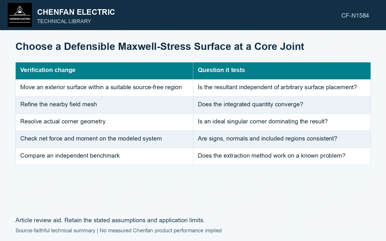
| Verification change | Question it tests |
|---|---|
| Move an exterior surface within the same suitable air region | Is the resultant independent of arbitrary surface placement? |
| Refine the nearby field mesh | Does the integrated quantity converge? |
| Resolve actual corner geometry | Is an ideal singular corner dominating the result? |
| Check net force and moment on the modeled system | Are signs, normals and included regions consistent? |
| Compare an independent benchmark | Does the extraction method work on a known problem? |
A closed exterior surface can provide a stable whole-body resultant where the geometry permits it. It does not necessarily reveal how force is distributed between internal contacts. The local structural load still needs a compatible interpretation.
Require surface invariance and mesh convergence
The following values and the 1% acceptance criterion are assumptions for a numerical verification example. Two valid air surfaces, A and B, enclose the same body. Suppose the project acceptance rule requires both the surface-to-surface spread and the change from the preceding mesh to be no greater than 1%.
| Mesh | Surface A resultant | Surface B resultant | Surface spread |
|---|---|---|---|
| Coarse | 101.8 N | 94.6 N | 7.33% |
| Fine | 98.9 N | 98.1 N | 0.81% |
The spread is calculated as |FA − FB| divided by their mean. Refinement reduces that spread from 7.33% to 0.81%, so the fine solution passes the surface-placement test. However, the mesh changes, each normalized to its fine-mesh magnitude, are 2.93% on surface A and 3.57% on surface B. The force therefore remains unconverged under the stated 1% rule; another mesh level is required. Surface agreement alone would have produced the wrong acceptance decision. Systematic mesh-convergence analysis must be performed on the desired force quantity [3].
Compare resultants before transferring peaks
Track the integrated force vector and moment, not only their magnitudes. A sign reversal or changing torque can expose a normal-direction mistake that a scalar force plot hides.
Use several mesh levels and surface placements. If the resultant stabilizes while a corner peak keeps increasing, report the peak as unresolved rather than treating the largest value as physical contact pressure. Do not smooth it merely to obtain a more attractive contour.
For a joint with a narrow air region, ensure that the field solution and integration resolve that region. Moving an integration surface across a material interface changes the formulation question, so it is not a valid invariance test unless the corresponding material-force terms are included.
The dependable output is a load with a defined free body, direction, moment and demonstrated numerical sensitivity—not a colorful peak contour.
Technical references
- Field Precision LLC, Theory and Applications of the Maxwell Stress Tensor, undated.
- COMSOL AB, AC/DC Module User’s Guide: Computing Electromagnetic Forces and Torques, version 6.4, Maxwell Stress Tensor; Maxwell Stress Tensor in Virtual Gap.
- COMSOL AB, Electromagnetic Forces on Parallel Current-Carrying Wires, Application Library, version 6.4, Results and Discussion.