

The supplier may report a limb axis relative to the core’s support face. The OEM may align its winding fixture from a base frame or assembly stop. Even when both dimension reports are correct, those axes can disagree because their references have never been related.
Identify transfer features that both sides can access and measure in the relevant assembly state. They should remain stable through packing, handling and fixture setup. A temporary chalk mark or a movable sheet edge is a weak coordinate reference.
Define the relationship mathematically
For an unchanged rigid assembly, a point measured in supplier coordinates can be expressed in fixture coordinates as pF = R pS + t. Here R is a rotation matrix, t a translation vector in millimetres, and pS and pF are corresponding point-coordinate vectors.
The transformation must be established from identified physical features. Three noncollinear point correspondences can define an ideal rigid relationship when their identities are unambiguous. More distributed features allow residual checks and improve the assessment of measurement error. Nearly collinear or clustered references provide weak rotational information.
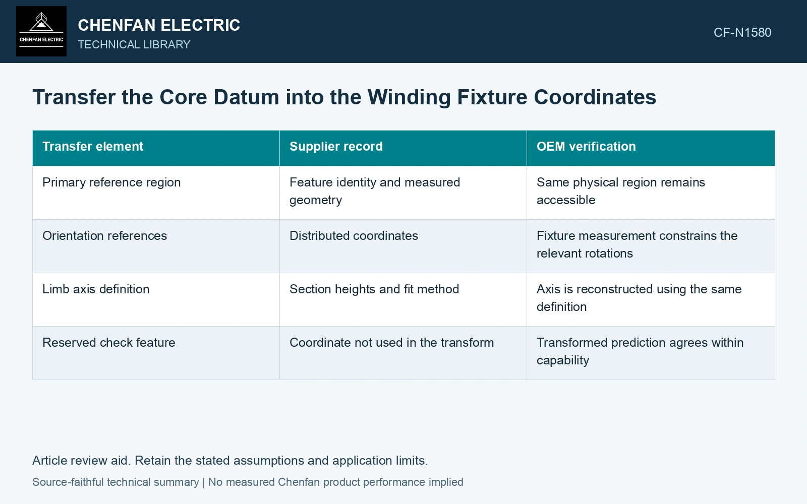
| Transfer element | Supplier record | OEM verification |
|---|---|---|
| Primary reference region | Feature identity and measured geometry | Same physical region remains accessible |
| Orientation references | Distributed coordinates | Fixture measurement constrains the relevant rotations |
| Limb axis definition | Section heights and fit method | Axis is reconstructed using the same definition |
| Reserved check feature | Coordinate not used in the transform | Transformed prediction agrees within capability |
Check the transformation before blaming the core
Use some features to establish R and t and reserve others to test the result. Compare the predicted positions of the reserved features with their measured fixture coordinates. A low fit residual on the defining features alone is not independent confirmation.
If residuals vary systematically across the assembly, investigate reference identity, fixture alignment and possible deformation. A rigid transform cannot correct a core that changed shape after unclamping or seating. Those states require a geometric comparison, not more freedom in the coordinate fit.
Apply the checked transformation to the limb envelope and the intended insertion path. This shows whether a mismatch comes from global location, axis orientation or local core shape. Adjustments to the fixture should follow the permitted assembly design rather than simply moving it until one section appears centered.
Retain the coordinate definitions with the dimensional results. A limb diameter without its axis reference is incomplete for a constrained insertion task. Likewise, a fixture coordinate without the physical datum identity cannot be reproduced at the supplier.
When the transfer is correct, the trial fit becomes a useful functional test of the remaining geometric assumptions. When it is undefined, a failed fit mixes datum mismatch with product geometry, making rework harder to target and encouraging unnecessary changes to an otherwise conforming core.
Check the transferred axis against one-sheet movement
Use 23ZH90 nominal thickness 0.23 mm [1] to represent an assumed one-sheet datum shift. Other assumptions: a rigid core, a 1,000 mm lever arm, a 0.05° rotation error and a 1.00 mm lateral fit margin. Rotation contributes 1,000 sin(0.05°) = 0.873 mm; adding the aligned 0.23 mm translation gives 1.103 mm. That exceeds the assumed margin by 0.103 mm, whereas either contribution alone would fit. Recheck the transfer features before restacking. Treat transformation and feature-extraction uncertainty together; a low residual on fitted points excludes neither datum bias nor deformation [2].
Manufacturing controls. Cut width, packet alignment, support seating and clamp sequence control whether datum features remain stable. Identify references on the load-bearing structure and record any sheet movement; a nominal-thickness calculation cannot certify the actual transfer geometry.
References
- Nippon Steel Corporation, Grain-Oriented Electrical Steel Sheets, catalogue D004je_03_202004, 2020, Specifications; Size and Form Tolerances.
- JCGM, JCGM 100:2008, Evaluation of measurement data — Guide to the expression of uncertainty in measurement, 2008.