

A horizontal core measurement includes the core’s response to gravity in that position. If the drawing describes the seated vertical assembly, the difference between those poses may be mistaken for permanent misalignment.
The amount of movement depends on support locations, clamping and the way sheets share load. A laminated assembly should not automatically be modeled as a homogeneous solid beam. Interfaces can slip, contact can change, and local packets may respond differently from the overall frame.
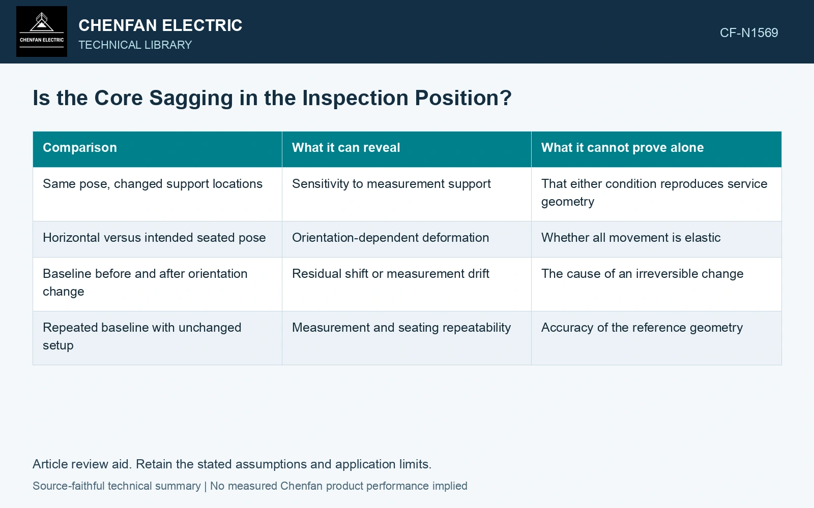
Compare conditions that answer one question
Begin with a documented baseline in the pose relevant to the controlled dimension. Record support points, restraint state and coordinate references. If a horizontal measurement is necessary for access, define how its support condition will be related to that baseline.
| Comparison | What it can reveal | What it cannot prove alone |
|---|---|---|
| Same pose, changed support locations | Sensitivity to measurement support | That either condition reproduces service geometry |
| Horizontal versus intended seated pose | Orientation-dependent deformation | Whether all movement is elastic |
| Baseline before and after orientation change | Residual shift or measurement drift | The cause of an irreversible change |
| Repeated baseline with unchanged setup | Measurement and seating repeatability | Accuracy of the reference geometry |
Use approved handling procedures for every pose change. The comparison is a measurement study, not permission to lift or rotate a core in an unqualified way.
Look for a reversible shape pattern
Measure several sections through the span. Gravity-related movement often produces a spatial pattern rather than a constant coordinate offset. Retain the section positions and compare the same physical features in each condition.
When returning to the baseline, reestablish the datums independently. Carrying over a transformed coordinate system can conceal a seating change. Compare both global position and shape relative to the newly established references.
If the horizontal shape changes with support spacing and returns within the measurement capability, support-induced deformation is a credible explanation. If the shape fails to return, inspect clamp movement, sheet slip and the reference setup before attributing the residual to permanent core damage.
A beam estimate can help plan the experiment by showing which spans may be sensitive. It becomes a correction only after the assembly model and boundary conditions have been validated against measurements. Subtracting a theoretical sag curve from every point otherwise risks removing a real shape error.
For routine inspection, choose a support arrangement that gives stable results and represents the intended dimension sufficiently well. Document contact locations so that another inspector can reproduce it. Avoid simply adding supports wherever the scan appears low; that can force the part toward the desired shape.
The acceptance record should name the pose to which its geometry applies. A core can have one horizontal envelope and a different seated envelope without either reading being false. The drawing requirement and assembly function determine which one controls the decision.
Estimate support sensitivity without inventing stack stiffness
The catalogue assumed density for 23ZH90 is 7,650 kg/m³ and nominal thickness is 0.23 mm [1]. Assume 100 sheets, each 0.10 m wide and 1.00 m long: steel volume is 0.00230 m³ and mass 17.595 kg. With assumed gravitational acceleration 9.81 m/s², distributed weight is 172.61 N/m. For an assumed simply supported equivalent stiffness EI = 10,000 N·m², the beam estimate 5qL⁴/(384EI) gives 0.225 mm sag over 1.00 m. A second idealized 0.80 m span, with no loaded overhang, gives 0.092 mm at the same q and EI. Use this 59% predicted reduction to plan a support comparison, then measure it; equivalent stiffness and its uncertainty need validation [2].
Manufacturing controls. Packet contact, clamp pressure, support spacing, layer slip and joint restraint determine real bending response. Catalogue density estimates dead load; it does not make a laminated core a bonded solid beam.
References
- Nippon Steel Corporation, Grain-Oriented Electrical Steel Sheets, catalogue D004je_03_202004, 2020, Specifications; Size and Form Tolerances.
- JCGM, JCGM 100:2008, Evaluation of measurement data — Guide to the expression of uncertainty in measurement, 2008.