

A joint-region magnetic map can contain two kinds of boundary: crystallographic boundaries within the steel and geometric boundaries between laminations. They should not be modeled as the same feature. A grain boundary changes local material orientation and microstructural conditions. An assembly clearance changes the physical magnetic path.
Begin with a local orientation and geometry map. Identify which grains are adjacent in the observed sheet and where the assembly joint lies relative to them. An average texture descriptor cannot reconstruct that local neighborhood.
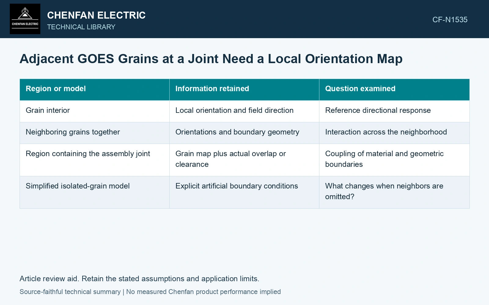
Keep neighbor identity in the comparison
Record the orientation of each characterized grain relative to rolling direction and the imposed magnetic direction. Document the observed boundary and any local surface preparation. If the map covers only one surface, mark the uncertainty in the through-thickness neighborhood.
Choose a comparison that addresses adjacency. A local response measured in a grain’s interior and another response near its boundary may reveal a spatial difference, but other factors such as stress or geometry can contribute. They must remain in the interpretation.
| Region or model | Information retained | Question examined |
|---|---|---|
| Grain interior | Local orientation and field direction | Reference directional response |
| Neighboring grains together | Orientations and boundary geometry | Interaction across the neighborhood |
| Region containing the assembly joint | Grain map plus actual overlap or clearance | Coupling of material and geometric boundaries |
| Simplified isolated-grain model | Explicit artificial boundary conditions | What changes when neighbors are omitted? |
An isolated-grain calculation should not be treated as a measurement of the same grain in its actual neighborhood. Its boundaries are part of the hypothesis being tested.
Compare field patterns before aggregate loss
A local model can predict redistribution that contributes little to a bulk measurement. Evaluate the spatial field pattern with a method of suitable resolution and known averaging. Retain component directions and probe or observation geometry.
Check whether the model represents directional material response, local stress and the actual assembly clearance. Fitting bulk loss by adjusting one grain parameter can compensate for an incorrect joint boundary. Use an independent local observation to discriminate those explanations.
Separate characterization from a manufacturing verdict
One unusual neighbor pair cannot establish the quality of an entire coil or core. The study’s sampling strategy determines whether the observation is a specific local feature or evidence for a broader distribution. Keep that distinction visible.
Likewise, a local grain-coupling result does not replace finished-joint evaluation. Assembly can change restraint and field direction even when the underlying grain map remains the same.
Align grain orientation, joint geometry and magnetic-component maps in one coordinate frame. Check whether the observed pattern follows the mapped boundary or the joint gap before assigning it to intergrain coupling.
Technical references
- Materials / MDPI. Magnetostrictive Properties of the Grain-Oriented Silicon Steel Sheet under DC-Biased and Multisinusoidal Magnetizations.
- NIST. NCAL: Diffraction Stress Measurement Under Applied Load.