

An X-ray instrument can return a fitted stress value even when the available diffraction data do not constrain every component equally. For GOES, strong crystallographic texture makes the usable reflections and specimen orientations part of the evidence, rather than merely acquisition settings.
Diffraction measures lattice spacings. Stress is inferred from their changes using a reference and a suitable elastic relationship. Keep those steps separate so that a polished stress map does not hide an uncertain lattice reference or a poorly identified tensor component.
Record what the orientation set actually measures
Choose reflections and specimen tilts with the method specialist. Document where diffraction peaks are usable, weak, overlapped or absent. Missing coverage should remain visible. Removing inconvenient observations without examining why they differ can produce an apparently smooth fit that represents a selected grain population.
NIST’s applied-load diffraction work describes near-surface stress-tensor measurements, selected reflections and orientation-dependent strains in sheet metals, including strongly textured materials. That supports the measurement logic. It does not supply calibration constants for an arbitrary GOES grade.
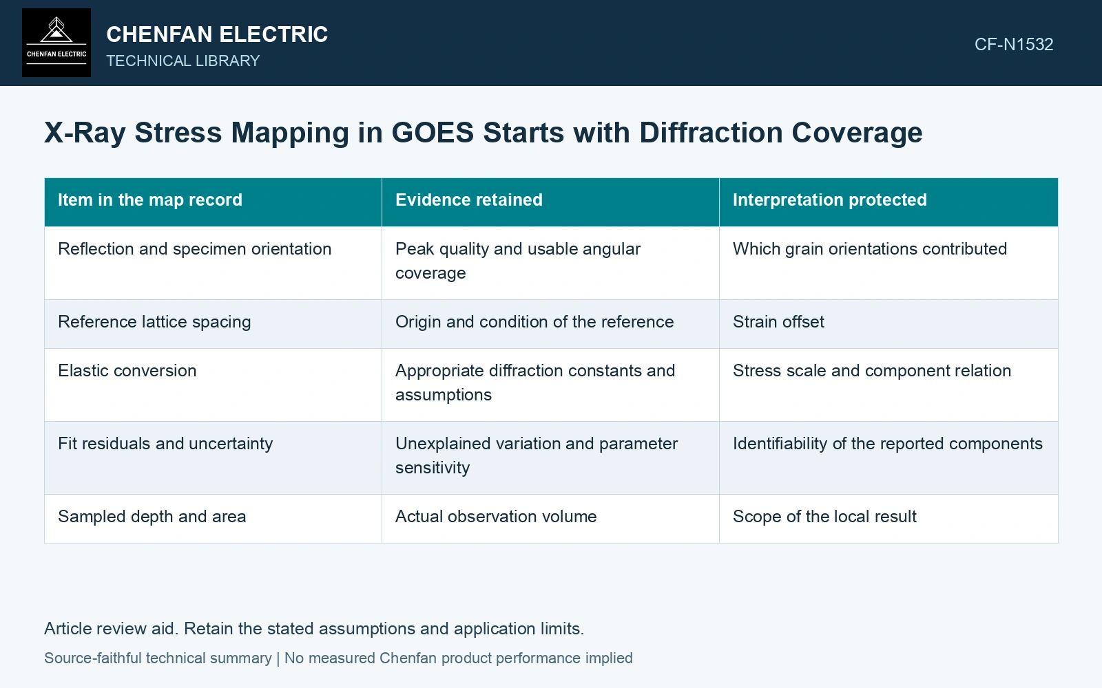
| Item in the map record | Evidence retained | Interpretation protected |
|---|---|---|
| Reflection and specimen orientation | Peak quality and usable angular coverage | Which grain orientations contributed |
| Reference lattice spacing | Origin and condition of the reference | Strain offset |
| Elastic conversion | Appropriate diffraction constants and assumptions | Stress scale and component relation |
| Fit residuals and uncertainty | Unexplained variation and parameter sensitivity | Identifiability of the reported components |
| Sampled depth and area | Actual observation volume | Scope of the local result |
The record should distinguish a component with weak sensitivity from one measured with adequate directional coverage. Both can appear as numbers in the same software output.
Separate macroscopic stress from grain-scale response
Different crystallographic populations can experience different elastic strains under the same macroscopic loading. A diffraction observation samples the populations that satisfy the measurement geometry. Converting that response into a sheet-level stress requires a justified model, especially in a textured material.
Compare suitable reference loading or independent strain information where available. Test whether the selected reflection and conversion reproduce a known mechanical state before relying on them for an unknown residual field. Surface preparation also needs assessment because coating removal or polishing can modify the state being measured.
Map the uncertainty alongside the stress
Repeat selected positions and orientations. Examine how fitted components change when the usable orientation set is varied within a justified analysis. A large change can indicate poor constraint, an inadequate conversion model or heterogeneity requiring further investigation.
Do not extend a near-surface observation to the full sheet thickness without evidence. Likewise, a point at one edge cannot establish the stress distribution around an entire joint.
The deliverable should contain the stress map, its sampling geometry and an orientation-coverage map. That combination allows a core engineer to distinguish measured spatial variation from an algorithm’s interpolation across regions or tensor components that the diffraction evidence did not adequately resolve.
Technical references
- NIST. NCAL: Diffraction Stress Measurement Under Applied Load.
- NIST publication record. Residual stress determination by diffraction: Modeling and applications.