

Neutron diffraction can investigate lattice strain inside engineering materials, but a reading from a core packet does not automatically describe an individual lamination. The incident and diffracted beam apertures define a gauge volume. Several steel layers and non-steel intervals may intersect that volume.
NIST’s measurement principles describe volume-averaged lattice spacings and the role of specimen orientation in resolving stress directions. For a laminated packet, the interpretation must start with which material and layers actually contribute diffraction signal in the selected geometry.
Draw the gauge volume through the stack
Record beam directions, aperture geometry and specimen position. Overlay the gauge volume on the actual sheet and spacer arrangement. State how many layers it intersects and whether the volume lies fully inside the specimen at every measurement position.
A scan approaching an edge can sample a changing material volume. That change can affect the result independently of the intended stress variation. Sampling geometry must therefore accompany the map, especially where a packet has stepped boundaries or cooling passages.
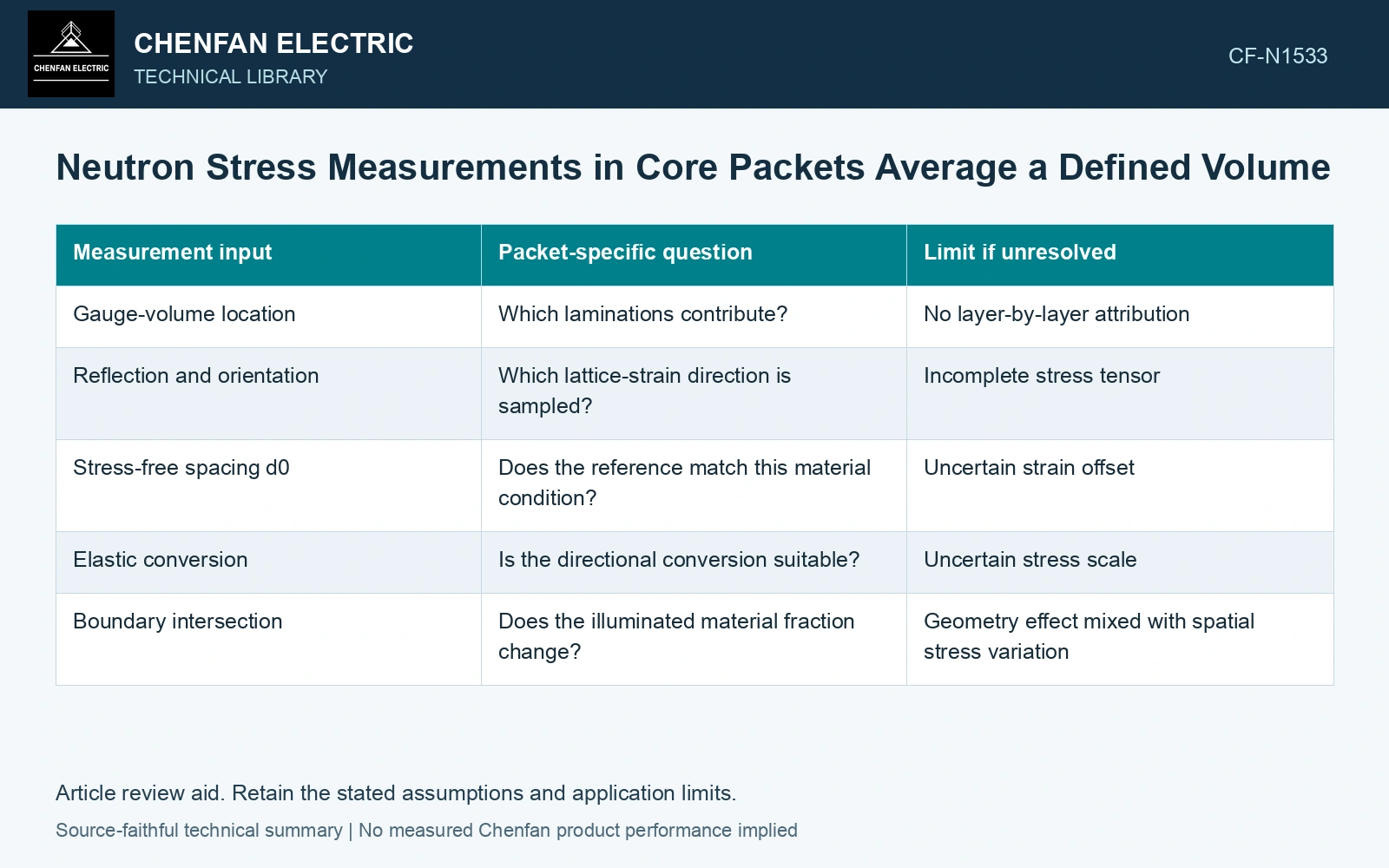
| Measurement input | Packet-specific question | Limit if unresolved |
|---|---|---|
| Gauge-volume location | Which laminations contribute? | No layer-by-layer attribution |
| Reflection and orientation | Which lattice-strain direction is sampled? | Incomplete stress tensor |
| Stress-free spacing d0 | Does the reference match this material condition? | Uncertain strain offset |
| Elastic conversion | Is the directional conversion suitable? | Uncertain stress scale |
| Boundary intersection | Does the illuminated material fraction change? | Geometry effect mixed with spatial stress variation |
The measurement is not simply an arithmetic average of all stresses inside a box. Diffraction weighting and crystallographic texture affect which grains contribute to the reported spacing.
Preserve the stress-free reference
Lattice strain is commonly expressed as epsilon = (d − d0)/d0, where d is measured spacing and d0 is the suitable stress-free reference spacing. Both lengths must use the same units; strain is dimensionless. An error in d0 creates an apparent strain offset.
The reference may require representative material coupons or another justified approach. Record material identity, temperature and treatment condition. An unrelated steel reference cannot be assumed to share the same spacing and microstructural state.
Do not call lattice stress contact pressure
Diffraction observes elastic lattice response in the steel. Inferring interlayer contact pressure requires a mechanical model and sufficient directional evidence. A measured in-plane component does not directly report the normal pressure between coatings. The packet can also contain residual sheet stress independent of assembly contact.
Combine the research result with known assembly loads and independent mechanical observations where the purpose is to identify those contributions. Consider whether changing the packet restraint changes the measured response reproducibly.
Record the gauge volume, material reference and reflection coverage with each lattice-strain or stress result. A bulk reading may inform the packet assessment, but it cannot resolve individual lamination stresses or interface pressures below that measurement volume.
Technical references
- NIST. Principles of Neutron Stress Measurements.