

Short answer
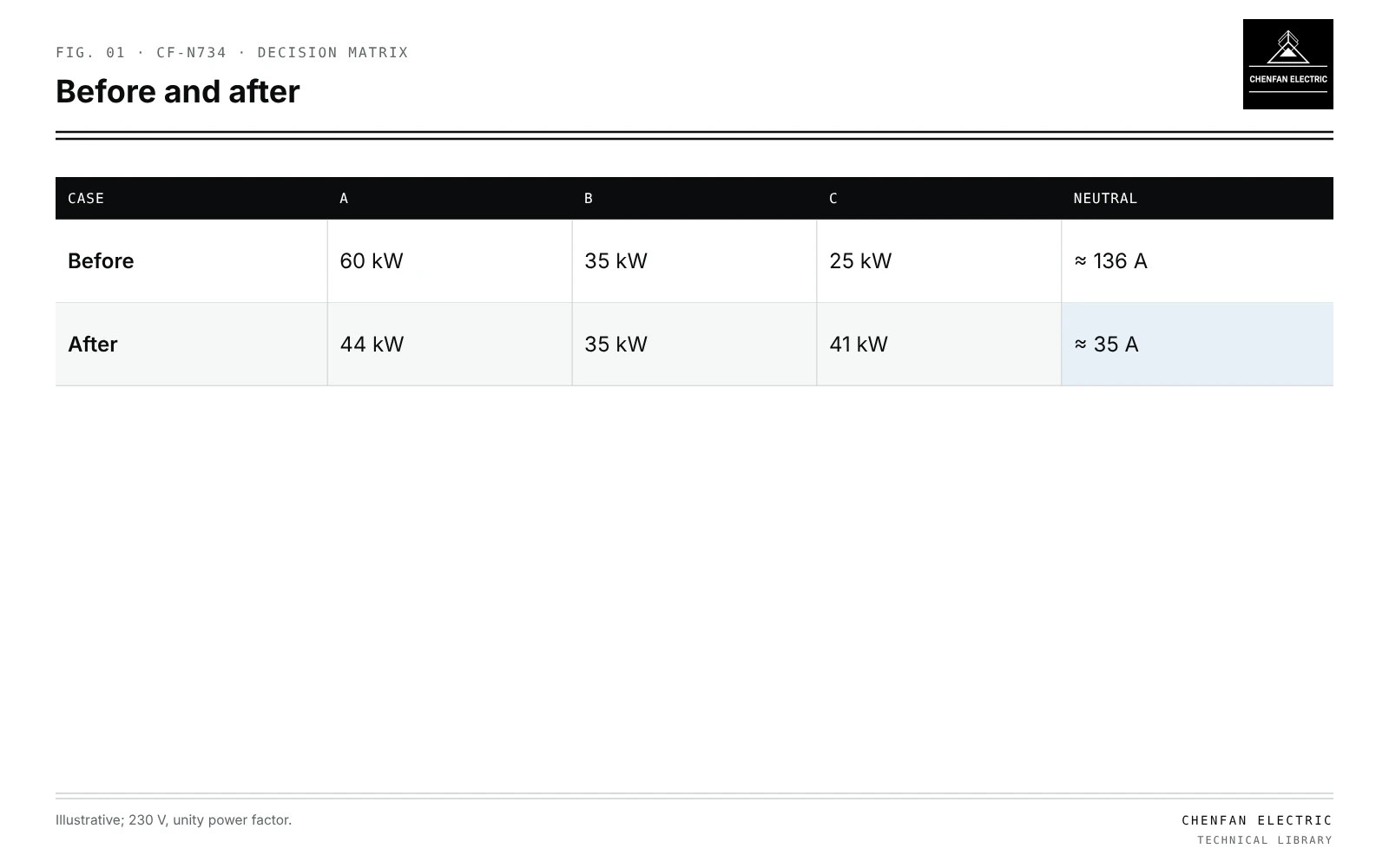
Transformer phase swapping optimization balances single-phase load across the three phases of a distribution transformer by deciding which customers to move to which phase. The decision variables are the phase assignments of customers that can actually be moved; fixed customers stay where they are. Objectives include reducing neutral current, equalising phase loading and raising the lowest end-of-line voltage, usually with a limit on the number of moves because each involves field work. In an illustrative transformer with phase loads of 60, 35 and 25 kW at 230 V and unity power factor, neutral current is about 136 A; moving two 8 kW customers from phase A to phase C gives 44, 35 and 41 kW and about 35 A. Optimisation relies on reliable phase identification first, and any field change must go through the operator’s approval process.
Problem formulation
| Case | A | B | C | Neutral |
|---|---|---|---|---|
| Before | 60 kW | 35 kW | 25 kW | ≈ 136 A |
| After | 44 kW | 35 kW | 41 kW | ≈ 35 A |
- Variables: phase assignment of each movable customer.
- Fixed: customers whose phase cannot change, three-phase loads.
- Objectives: minimise neutral current, maximum phase loading, or voltage unbalance, often combined.
- Constraints: maximum moves, phase conductor ratings, end voltage limits, service type.
- Data: time-varying loads per customer, not only peak values.
Combinatorial problems of this kind are solved by integer programming or heuristics; small transformers can be enumerated.
Illustrative effect
Illustrative example. 230 V phase-to-neutral; unity power factor; phase loads 60, 35 and 25 kW before; two 8 kW customers moved from A to C. Values chosen for demonstration.
Before: currents ≈ 261, 152 and 109 A.
I_N ≈ |261 − (152 + 109)/2 + j0.866 (109 − 152)| ≈ 136 A
After: 44, 35, 41 kW → ≈ 191, 152, 178 A.
I_N ≈ |191 − 165 + j0.866 (178 − 152)| ≈ 35 A
Neutral current falls by about three quarters with two moves.
Using time series
Peak-only balancing may unbalance other hours. Optimising over a representative set of intervals, or over daily profiles, gives assignments that work across the day. AMI interval data provide this; see calibrating transformer load allocation with AMI data.
Phase identification first
Optimisation based on wrong phase labels moves customers that are already on the target phase. Reliable identification is a prerequisite; see phase allocation using transformer-side smart-meter data and transformer phase mapping from GIS.
Effects to verify
- Neutral current and neutral voltage; see unbalanced load flow with an explicit neutral.
- Phase loading against transformer and cable ratings.
- End voltages on each phase.
- Losses before and after.
Identification versus implementation
The optimisation produces candidate moves. Whether to carry them out, when and how, is an operational decision requiring field verification, safety procedures and customer notice.
What this article does not cover
It gives no instructions for changing customer phases in the field; such work needs operator approval and procedures.
Where this reasoning stops. Unity power factor and lumped loads are assumed; real studies use measured profiles.
Practical takeaway
Frame phase swapping with movable customers as variables, optimise neutral current and voltages over time series with a move limit, confirm phase identification first, and pass candidate moves to field approval.