

Short answer
Capacitor overload background harmonics come from upstream, not from the plant itself. A capacitor’s reactance falls with frequency, so a harmonic voltage of order h already present on the supply drives a current h times larger, relative to the capacitor’s fundamental current, than the same percentage of fundamental voltage would. In an illustrative case, 3 % 5th harmonic voltage on the supply drives 15 % 5th harmonic current into a plain capacitor bank. If the bank and the supplying transformer form a parallel resonance near the 5th, an amplification of four times gives 60 %, and the capacitor’s RMS current rises to about 1.17 per unit, before bus overvoltage and capacitance tolerance are added; the actual allowable current must come from the capacitor rating and applicable specification. Local and upstream sources share capacitors through frequency-dependent impedances. Absence of nonlinear load in the plant does not mean absence of harmonic risk.
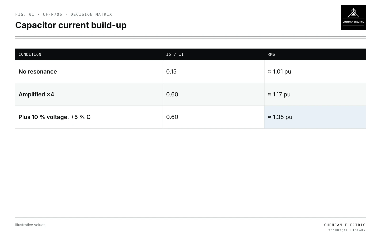
Current from harmonic voltage
| Condition | I5 / I1 | RMS |
|---|---|---|
| No resonance | 0.15 | ≈ 1.01 pu |
| Amplified ×4 | 0.60 | ≈ 1.17 pu |
| Plus 10 % voltage, +5 % C | 0.60 | ≈ 1.35 pu |
I_h / I_1 = h × U_h / U_1
Illustrative example. LV bus with background 5th harmonic voltage 3 % from the MV network; plain capacitor bank; plant has no significant nonlinear load. Values chosen for demonstration.
I_5 / I_1 = 5 × 0.03 = 0.15
Irms = sqrt(1 + 0.15^2) ≈ 1.011 pu
Without resonance, this is modest. With the bank in parallel resonance with the transformer near the 5th, the bus 5th voltage may be amplified, say four times:
I_5 / I_1 ≈ 0.6; Irms ≈ sqrt(1 + 0.36) ≈ 1.17 pu
Add 10 % bus overvoltage and +5 % capacitance tolerance and the RMS current approaches 1.35 pu.
Local versus upstream sources
| Source | Path into capacitor |
|---|---|
| Local nonlinear load | Harmonic current divides between capacitor and transformer/source |
| Upstream voltage distortion | Capacitor and transformer form a divider for the harmonic voltage |
| Both | Phasor combination; worst case may add |
Frequency-dependent impedances set the division. Transformer impedance at harmonic order h is roughly h times its fundamental reactance, with damping that varies with frequency; see resonance scans with frequency-dependent transformer damping.
Ratings to check
- RMS current including harmonics, against the actual capacitor’s declared continuous and temporary current limits, with the specified voltage and tolerance basis.
- Peak voltage including harmonics.
- Temperature in the enclosure.
- Fuses and contactors for RMS and harmonic current.
Remedies
- Detuning reactors, which make the branch inductive above its tuning point; see detuning factor in transformer-fed capacitor banks.
- Tuned filters where absorption is wanted; see single-tuned and damped filters on transformer buses.
- Measuring background distortion with the bank out, before design.
Changes in transformer configuration shift resonance; see harmonic amplification after one transformer is removed.
What this article does not cover
It does not equate absence of nonlinear load with absence of harmonic risk.
Where this reasoning stops. Amplification factor is illustrative; real values come from frequency scans and measurement.
Practical takeaway
Measure background voltage distortion before installing plain capacitors, calculate harmonic current with possible resonance amplification, and use detuned or filter designs when RMS current approaches limits.
Reference framework
- IEC 60831-1, Shunt power capacitors of the self-healing type for a.c. systems up to 1 kV.
- IEEE 1036, Guide for the application of shunt power capacitors.