

Short answer
Neutral-to-earth voltage in a transformer-supplied building is a measurement between two defined points, not a direct measure of transformer quality. Load current can create voltage drop along the neutral, while the protective reference has its own connection and potential. Interpret the reading with the actual bonding arrangement, current, impedance and operating state. Neither a small reading nor a nonzero reading alone establishes safety or a fault.
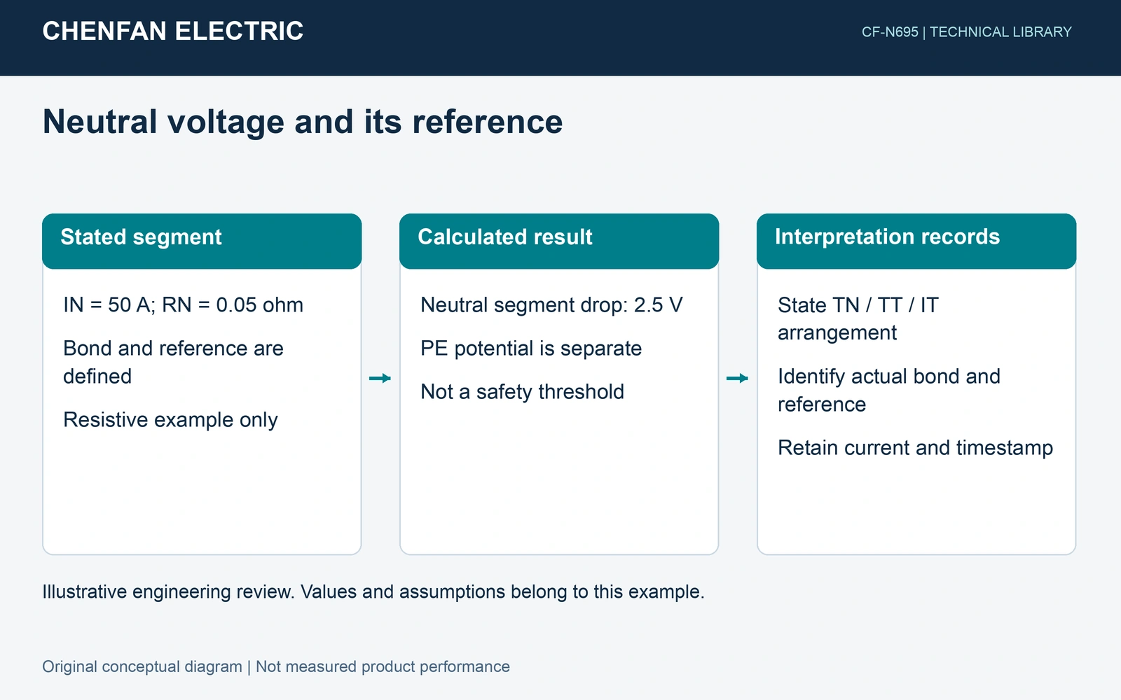
Name both measurement points
Record the neutral point, protective-earth or other reference point, and the intended neutral-to-earth bond shown on the installation drawings. State whether the documented arrangement is TN, TT or IT and identify any PEN separation or alternative-source mode. The same label “earth” does not prove that two remote references share the same potential.
In a simplified bonded arrangement with negligible protective-reference voltage drop, the downstream neutral potential can reflect the neutral-conductor drop back to the bond. Parallel paths, additional connections and an elevated reference potential can change that interpretation. A transformer vector-group label does not resolve those installation details.
A stated neutral-segment calculation
Assumptions. Fundamental neutral current is 50 A through a defined 0.05 Ω resistive segment between a known bond and the downstream point. The protective reference is assumed to remain at the bond potential. These values are synthetic and exclude other paths.
ΔVN = INRN = 50 × 0.05 = 2.5 V
The result describes the assumed conductor segment. It is not a permitted neutral-to-earth voltage, a touch-voltage conclusion or proof that the protective path is intact. If the protective reference also shifts, the measured voltage is the difference between the two local potentials.
Retain phase relationships and frequency
Fundamental unbalance and triplen harmonic current can both load a neutral. For each frequency, use the relevant current phasor and conductor impedance. Combine different-frequency components through an appropriate RMS process; do not add their voltage magnitudes as though all components share one phase and frequency.
An explicit neutral representation helps distinguish customer phase-to-neutral voltage from phase-to-earth voltage. It also makes the assumed grounding locations visible. A model that fixes every neutral point to zero cannot reproduce a downstream neutral drop.
Use examples within their installation scope
Fluke’s receptacle article illustrates load-related neutral-conductor drop in a 120 V US-style circuit. Its typical reading comments are not a worldwide acceptance line for buildings supplied at other voltages or with different earthing arrangements. This article uses that explanation of conductor drop, without importing its example thresholds or receptacle procedure.
| Record | Why it matters |
|---|---|
| Actual bond and reference | Defines the measured difference |
| Load and neutral current | Connects voltage with operating duty |
| Phase and harmonic data | Separates frequency-dependent effects |
| Source mode and timestamp | Identifies the current network state |
Any investigation should follow the approved procedure and be handled by qualified personnel. Do not disconnect a protective conductor or add a neutral-earth bond merely to reduce a reading. Use the full installation assessment and applicable local requirements to decide what the result means.
Sources and scope
- Fluke, Diagnosing power problems at the receptacle, original manufacturer article. Its 120 V receptacle example was reviewed for the neutral-conductor IR-drop explanation, not as a global acceptance criterion.