

Short answer
Capacitor terminal voltage in a detuned bank is higher than bus voltage. At fundamental frequency, the series reactor and capacitor form a divider in which the capacitor voltage is bus voltage divided by (1 − p), where p is the detuning factor. Harmonic currents flowing through the branch add voltage across the capacitor equal to each harmonic current times the capacitor’s fundamental reactance divided by the harmonic order. In an illustrative 400 V bus with p = 7 %, the fundamental capacitor voltage is about 430 V; a 5th harmonic current of 15 % of rated current adds about 13 V and a 7th of 5 % adds about 3 V. The arithmetic sum of the component peaks is a conservative voltage bound; the actual waveform peak depends on harmonic phase angles. RMS current, frequency-dependent losses and thermal conditions must also be checked. Ratings must cover the capacitor, reactor and switching devices for their own voltages, not the bus voltage alone.
Fundamental voltage
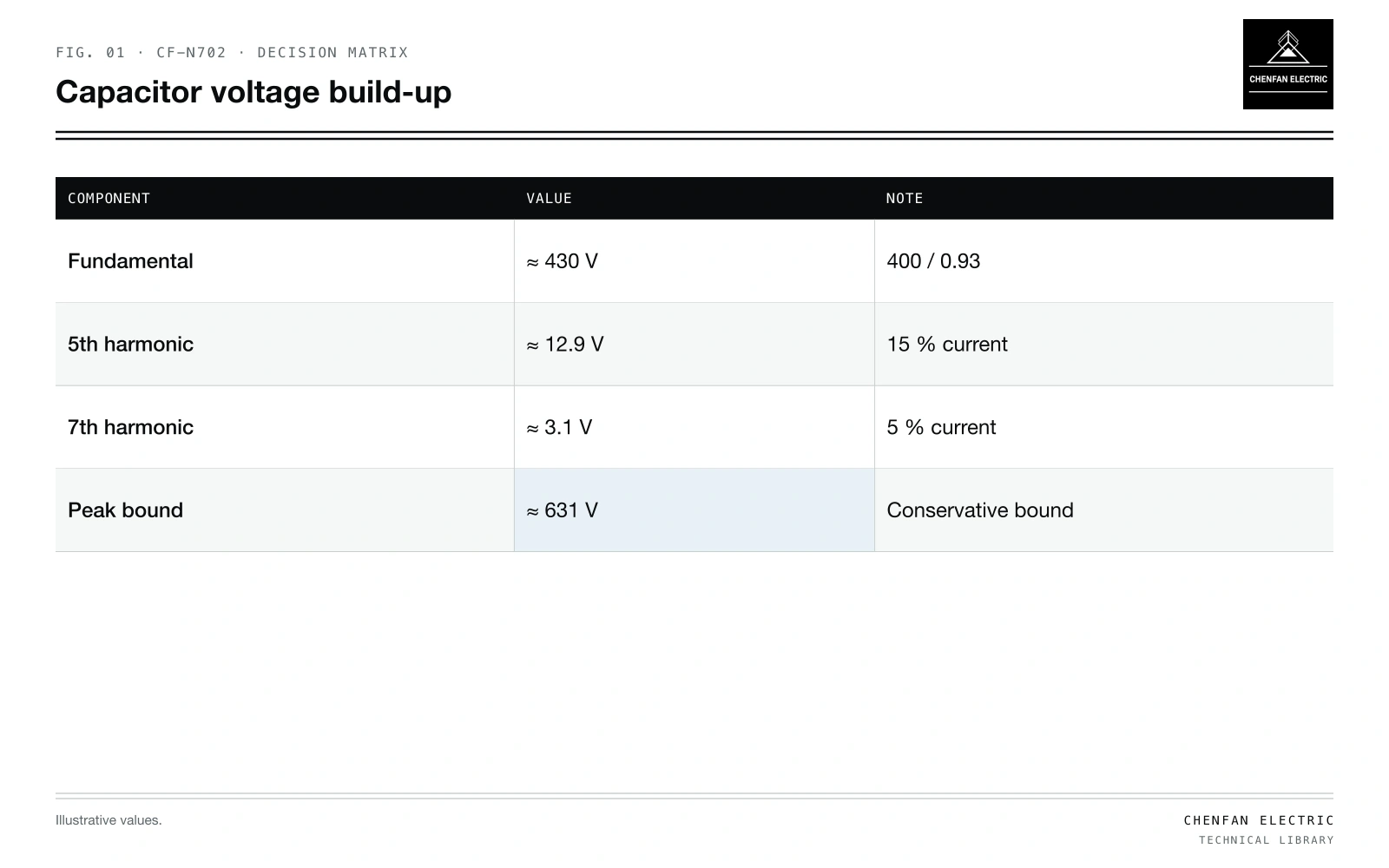
| Component | Value | Note |
|---|---|---|
| Fundamental | ≈ 430 V | 400 / 0.93 |
| 5th harmonic | ≈ 12.9 V | 15 % current |
| 7th harmonic | ≈ 3.1 V | 5 % current |
| Peak-sum bound | ≈ 631 V | Conservative phase-alignment bound |
UC1 = Ubus / (1 − p)
With p = 7 % and 400 V bus: U_C1 ≈ 430 V. The reactor sees U_bus × p / (1 − p) ≈ 30 V at fundamental. Detuning basics are in detuning factor in transformer-fed capacitor banks.
Harmonic voltage at the capacitor
UCh = I_h × XC1 / h
Illustrative example. 400 V bus, p = 7 %; capacitor rated current I_C at 430 V; harmonic currents in the branch: 5th 15 % and 7th 5 % of I_C. Values chosen for demonstration.
Using X_C1 = 430 V / I_C:
UC5 ≈ 0.15 × 430 / 5 ≈ 12.9 V
UC7 ≈ 0.05 × 430 / 7 ≈ 3.1 V
RMS ≈ sqrt(430^2 + 12.9^2 + 3.1^2) ≈ 430.2 V
peak-sum bound ≈ 1.414 × (430 + 12.9 + 3.1) ≈ 631 V
The RMS voltage rises little, while the peak-sum bound is about 3.7 % above the fundamental peak. Actual peak voltage depends on the harmonic phases. At +10 % bus voltage, the fundamental capacitor voltage increases by 10 %; harmonic contributions must be recalculated for the resulting operating case.
Ratings to check
| Component | Voltage to check | Current to check |
|---|---|---|
| Capacitor | Fundamental + harmonics, peak and RMS, at maximum bus voltage | RMS with harmonics |
| Reactor | Fundamental and harmonic voltage across it | RMS and peak, linearity |
| Contactor or switch | Bus voltage, capacitive duty | Inrush and RMS |
Capacitor standards define allowable overvoltage and overcurrent factors; check those for the actual unit. Background distortion from upstream raises harmonic currents even without local sources; see capacitor overload from background harmonics.
Maximum operating conditions
- Highest bus voltage expected, including light-load voltage rise.
- Worst harmonic spectrum across operating states.
- Capacitance tolerance at its high end, increasing current.
- Temperature effects on capacitance and reactor.
Measured kvar at acceptance also depends on these; see capacitor bank acceptance.
What this article does not cover
General principles of power-factor correction are not repeated here.
Where this reasoning stops. Harmonic currents are illustrative; real values come from harmonic studies or measurement.
Practical takeaway
Calculate capacitor voltage as bus voltage over (1 − p) plus harmonic contributions, check the peak-sum bound, actual waveform peak and RMS duty at maximum bus voltage, and rate each component for the voltage it actually sees.
Reference framework
- IEC 60831-1, Shunt power capacitors of the self-healing type for a.c. systems up to 1 kV.
- IEC 61642, Industrial a.c. networks affected by harmonics: application of filters and shunt capacitors.